Astronomie: Planetarium-Software “Guide”

Gehört zu: Astro-Software

Planetarium-Software “Guide”

Meine Anforderungen an Planetariumsoftware.

Neben Stellarium und  Cartes du Ciel “CdC” ist “Guide” eine bekante Planetariumsoftware für Windows-Computer.

Links in diesem Blog

Bestimmung der Grenzgröße

Website / Bezugsquelle

http://www.projectpluto.com/

Kosten

Die Software Guide soll jetzt (Version 9.1) kostenfrei sein (die Dokumentation kostet).

Dokumentation

x https://www.projectpluto.com/guide9.pdf

https://www.projectpluto.com/user_man/page01.htm

http://www.projectpluto.com/update8d.htm#scope_indicator

Zukunftssicherheit

Guide wird nicht mehr weiterentwickelt. Community klein.

Benutzeroberfläche

Etwas altmodisch und umständlich

Beobachtungsort

  • Einstellen: Menü -> Einstellungen -> Beobachtungsort
  • Anzeige:  Der aktive Beobachtungsort wird oben links im Titel des Windows angezeigt
  • Horizont-Objekte:  Menü -> Karte -> Hintergrund -> Horizont-Objekte   (siehe auch weiter unten die Datei “horizon.dat”)

Datum und Uhrzeit

  • Einstellen: Menü -> Einstellungen -> Eingabe der Zeit
  • Hier wird auch die Zeitzone und die Sommerzeit eingestellt
  • Anzeige:  Datum, Uhrzeit und Zeitzone werden (hinter dem Beobachtungsort)  oben links im Titel des Windows angezeigt
  • Alternativ: In der Legende (links unten)  auf die Zeile mit Datum und Uhrzeit klicken
  • Alternativ: eine Funktionstaste

Navigieren und orientieren  am (virtuellen) Sternenhimmel

  • Durch Klicken mit der Maus wird die Sternkarte dort als Mitte positioniert (bei gleicher Vergrößerung); so kann man Stück für Stück über den Himmel spazieren…
  • Ausrichten der Ansicht: Menue -> Karte -> Orientierung -> z.B. “Alt/Az”  (d.h. Horizont waagerecht, Zenith oben)
  • Mit dem Mausrad kann man die Karte verkleinern oder vergrößeren wobei 20 Zoom-Stufen möglich sind (oder stufenlos: Menue -> Extras -> Feste Stufen = aus)
  • Der Horizont kann mit Symbolen (z.B. ein großes “N” für Norden) und auch durch eine etwas höher stehende Kimmlinie (Häuser, Bebauung) relativ einfach bestückt werden. Siehe dazu den separaten Abschnitt unten in diesem Beitrag.
  • Ein einmal eingestellter Ausschnitt des Sternenhimmels mit allen dazugehörenden Einstellungen (Koordinatennetz, Beschriftungen, Ort, Datum,….) kann als sog. “Karte” abgespeichert werden und später wieder geladen werden…

Welche Objekte sollen angezeigt werden?

  • Sterne
  • Sernbeschriftungen: Menue -> Karte -> Sterndarstellungen    (Karte = Ansicht)
    • Man kann sogar die scheinbaren Helligkeiten als Beschrifung nehmen:  “Beschrift. bis Mag.”  dann bedeutet z.B. “944” einfach “mag 9,44”
    • Die schwächeren Sterne werden erst ab einer gewissen Vergrößerung angezeigt
    • Die Frage ist dann noch, welcher Sternkatalog eigentlich zu Grunde liegt….
  • Sternbildlinien
  • Sternbildnamen
  • Koordinatennetze:  Menue -> Karte -> Skalen    (Karte = Ansicht)
    • Aber: im Dialog “Skalen” kann man nicht einstellen, ob man äquatoriale oder azimutale Skalen etc. haben will
    • Erst wenn man im Dialog “Skalen” ein Häcken setzt oder entfernt bei z.B. “Gradnetz”, erst dann eröffnet sich einer neuer Dialog für Gradnetz, wo man äquatorial oder aziumutala oder… einstellen kann
  • Horizont, Ekliptik,….
  • Deep Sky Objekte (Messier, NGC,…)
  • DeepSky Bilder:  xxxx
  • Planeten, Kometen, Asteroiden,…
  • Milchstrasse
  • Künstliche Satelliten
    • Dazu benutzt Guide eine sog. TLE-Datei, die unter Menue -> Einstellungen -> TLE=xxx angegeben wird
    • Suchen/Finden von Erdsateliten Menue -> Finden -> Satellit dann öffnet sich ein Dialogfenster wo man einen Suchbegriff eingibt (Name oder Teil des Namens). Man erhält als Ergebnis eine Liste aller Satelliten (der eingestellten TLE-Datei) , bei denen der Suchbegriff vorkommt. Wenn man einen leeren Suchbegriff eingibt, bekommt man die gesamte Liste der Satelliten der TLE-Datei. In dieser Ergebnisliste kann man einen Satelliten durch Anklicken auswählen…
    • Zum Anzeigen von Erdsatelliten auf der Karte gibt man unter: Menue -> Karte -> Objektauswahl -> Satellit die Grenzgröße für die Satellitenanzeige an und ob man den Namen des Satelliten sehen will.

Suchen von Beobachtungsobjekten (Name, Koordinaten)

  • Menue -> Finden   (“Finden” engl. “Go To”)

Winkelabstände messen

  • Mit der rechten Maustaste klicken und ziehen, dann erscheint ein Popup-Fenster mit einigen Daten wie Abstand in Grad und in Bogenminuten, dem Orientierungswinkel und den Deltas in R.A. und Deklination

Gesichtsfeld-Rahmen (Sensorfeld bzw. Okular)

  • Menü -> Karte -> CCD-Rahmen:    Kästchen zum An- und Ausschalten des Rahmens
  • Objektiv-Brennweite:  Kann direkt im Fenster in Millimetern eingegeben werden
  • Sensorgröße: Kann nicht direkt eingegeben werden, man muss die (z.T. alten) Kamerabezeichnungen und deren Sensorgrößen kennen
    • APS-C Sensor (22,3 x 14,9mm)  = Canon EOS 50D
    • 1/3″ Sensor (4,80 x 3,60 mm) = ASI ZWO 120

Liste von Beobachtungsobjekten

  • Im Guide gibt es eine sog. “Private Objekt-Liste”, die im Menü-Punkt “Overlays” versteckt ist
  • Das zentrierte Objekt zur Liste hinzufügen: Menue -> Overlays -> Private Objektliste -> Hinzufügen
  • Objekt auf Sternkarte zeigen: Menue -> Overlays -> Private Objektliste -> Objekt aufsuchen
  • Teleskop …

Sternkataloge einbinden

???

Sternkarten ausdrucken

ja, sehr  gut.

ASCOM-Teleskop-Steuerung

Menü –> Einstellungen –> Teleskop-Parameter

Hier stellen wir ein, welche Montierung wir mit dem Computer verbunden haben:

  • Entweder ASCOM, dann folgt alles weitere in den ASCOM-Fenstern
  • Oder wir wählen eine COM-Schnittstelle aus und dann eine der direkt unterstützten Montierungen….

ich sehe halt nur nichts vom Teleskop. Wo kann man das einschalten, dass das Teleskop auch in der Sternkarte angezeigt wird?

einen direkten Hinweis auf das Teleskop gibt es in GUIDE nicht.

Die Lösung für mein Problem habe ich gerade von Sven gelernt. Sie findet sich hier:

http://www.projectpluto.com/update8d.htm#scope_indicator

Man muss unter Einstellungen Toolbar die Option “Toggle scope location indicator” aktivieren. Dann kann man die Anzeige (rotes Kreuz) einfach einschalten und sieht genau, wohin das Teleskop aktuell zeigt.

Wenn du im Teleskopfenster “Teleskop” drückst, schwenkt GUIDE das Teleskop auf das Objekt das du in GUIDE ausgewählt hast. Drückst du auf “GUIDE”, wechselt GUIDE auf den Himmelsausschnitt auf das das Teleskop gerade zeigt.

Definition des Horizonts für Guide

Das Anschalten der Horizont-Objekte geschieht durch:  Menü -> Karte -> Hintergrund -> Horizont-Objekte

Die Definition der Horizont-Objekte wird mittels der Text-Datei “horizon.dat”, die direkt im Guide-Ordner liegen sollte,  gemacht. Dort wird wird einfachen Befehlen die RGB-Farbe des Kimm-Bereichs (über der eigentlichen Horizontlinie) und dann rundum pro Zeile ein Wertepaar mit Azimut und Höhe der Kimmlinie (in Grad) eingegeben:

hor  R G B
az-1 alt-1
az-2 alt-2

az-n alt-n
hend

Also beispielsweise:

hor 63 16 16
0 16
35 22
100 18
145 26
320 16
340 11
360 16
hend

Definition und Plazierung von Horizont-Objekten

In der Text-Datei “horizon.dat” können weitere Befehle zum Zeichnen von Horizont-Objekten (als Polygonzüge) eingegeben werden

z.B. eine dreieckige Spitze beim Azimuth 45 Grad (Nord-Ost):

f  3   64 32 0     ; Es folgen 3 Punkte. Es soll die RGB-Farbe 64 32 0 zum Füllen verwendet werden
44 0      ; Punkt 1
45 5      ; Punkt 2
46 0     ; Punkt 3

z.B. ein Kreis (circle):
c  x y z

Oder auch der Aufruf (i = insert) eines Objekts aus der Text-Datei “objects.dat” mit seinem Namen:

i    objekt-name  az alt scale

Astronomie: Planetarium-Software “Cartes du Ciel” (Sky Chart)

Gehört zu: Astro-Software
Siehe auch: Planetariumsoftware., Stellarium, N.I.N.A.
Benutzt: Fotos aus Google Drive

Stand: 25.12.2022

Planetarium-Software “Cartes du Ciel”

Neben Stellarium und Guide ist Cartes du Ciel “CdC” die bekantesten Planetarium-Software für Windows-Computer, welche gern für die Planung von Beobachtungen benutzt wird.

Das Planetariumprogramm Cartes du Ciel ist kostenlos. Es wird auch “Sky Chart” genannt.

Ausserdem gibt es viele Apps für iOS und Android, die ähnliches leisten.

CdC High Lights

  • Mehrere Standorte können abgespeichert werden
  • Beobachtungsliste – Observation List
  • Teleskopsteuerung Goto und Sync über ASCOM  (aber nicht Kamera/Imager: dazu nehme ich APT): s.u.
  • Drucken von Auffinde-Karten

CdC Website / Bezugsquelle / Version

https://www.ap-i.net/skychart/en/start

Versionen

  • Version 4.2.1 vom 24. Nov 2019
  • Version 4.0 vom 19. März 2017

Kosten

Licensing has changed from Freeware to Open Source GPLv2.

Dokumentation

https://www.ap-i.net/skychart/en/documentation/start

Intuitive Benutzeroberfläche

Ganz gut: Fenster und Menüleisten a la Windows – deutlich besser als Guide

Aber etwas kompliziert.

Zukunftssicherheit

  • Es gibt Versionen für Windows, Mac OS und Linux.
  • Der Programmierer ist der Schweizer Patrick Chevalley.
  • Version 4.0 stammt vom März 2017
  • Version 4.2.1 ist vom Nov 2019

Installation und Einstellungen

Nach der Installation stelle ich noch einige spezielle Dinge ein.
Gespeichert wird Vieles davon in: C:\Users\<userid>\AppData\Local\skychart

  • Oberfläche (Sprache, Werkzeugleisten)
  • Beobachtungsorte: Hamburg, Handeloh, Kiripotib (Observatory Database?)
  • Horizont-Linien: D:\data\Ciel\horizon\horizon_Eimsbuettel.txt
  • Sternkataloge: Setup -> Catalog -> CdC Deep Sky: LBN, SH2
  • Gesichtsfelder: xxx

Server-Parameter einstellen

Für die Zusammenarbeit mit N.I.N.A. stellen wir folgendes in CdC ein:

Menüleiste -> Setup -> General -> Server:  Server IP-Port 3292

Beobachtungsorte einstellen und speichern

Sehr gut:

  • Menü -> Einstellungen -> Beobachtungsort
  • Es können mehrere Orte eingegeben und mit Zeitzone gespeichert werden. Auch kann der Horizont für jeden Ort lokal in einer sog. “Horizontdatei” (s.u.) angegeben werden

Beobachtungszeit und -datum einstellen

  • Menü -> Einstellungen -> Datum, Zeit
  • Mit Zeitzone

Navigieren und orientieren am (virtuellen) Sternenhimmel

Geht ganz gut

  • Zoomen (FoV): OK  mit  Mausrad (oder Leiste am rechten Rand)
  • Ausschnitt schieben:  OK mit der Maus  (Shift & Ziehen)
  • Himmelsrichtung (Nord, Ost, Süd, West): OK (über Symbol auf Leiste am rechten Rand und Menü: Karte -> Horizontansicht)
  • Einblenden von Koordinatennetzen: OK (über Symbole auf  Leiste am linken Rand und Menü: Karte -> Koordinatensysteme)
  • Beschriften von Himmelsobjekten s.u.

Welche Himmelsobjekte sollen angezeigt werden?

Menü: Karte -> Zeige Objekte  (Sterne, Deep Sky, Bilder, Nebel, Planeten, Asteroiden, Kometen, Milchstraße)

Sterne

  • Grenzhelligkeit: Menü: Einstellungen -> Karte, Koordinaten  -> Objektfilter -> Visuelle Grenzgröße
  • Allerdings müssen die anzuzeigenden Sterne in einem eingebundenen Sternkatalog (s.u.) enthalten sein.

Kometen

In Cartes du Ciel: Menüleiste -> Einstellungen ->Sonnensystem -> Reiter Komet -> Lade MPC Datei -> Lade MPC-Format Datei ->Herunterladen.

Man kann auch eine lokale Datei in CdC importieren (Daten vom MPC: https://minorplanetcenter.net//iau/Ephemerides/Comets/Soft00Cmt.txt)

 Zodiakallicht ???

Erdsatelliten (Künstliche Satelliten)

Da muss man in der oberen Leiste auf das Symbol “Ephemeris Calendar” klicken.

  • Bahnelemente
    • Obere Leiste: Symbol “Ephemerieden” (Kalender) -> Erdsatelliten
      In diesem Fenster dann:

      • Schaltfläche “TLE herunterladen”
      • Datum vom/bis eingeben
      • Schaltfläche “Aktualisieren”
  • Anzeige
    • In der Liste der jetzt angezeigten Satelliten Doppel-Klick auf die Zeile mit dem Satelliten, den man sehen möchte.
    • Datum und Uhrzeit springen dann um und die Spur des Satelliten wird gezeigt (ggf. Horizont am Beobachtungsort ausschalten).
    • Durch Klicken auf die Schaltfläche “Reset Chart” schaltet CdC wieder zurück auf Datum und Uhrzeit, die man vorher hatte.

To download the latest data you must register with www.space-track.org/login.pl There is a download button which will do the download automatically…

Suchen von Himmelsobjekten

  • Obere Symbolleiste:
    • Suchfeld
    • Lupe-Symbol   — gute Suche nach verschiedenen Objekttypen

Beschriftungen

  • Menü: Einstellungen -> Anzeige -> Beschriftungen
  • Beschriften von Himmelsobjekten:
    • Ja, prinzipiell über Menü -> Karte -> Beschriftungen (Ja/Nein)
    • Dann:                        Menü -> Einstellungen -> Anzeige -> Beschriftungen -> Objekt beschriften -> …
  • Da  schalte ich manchmal “Deep Sky Objekte” aus, wenn ich denen in einer Beobachtungsliste eine besondere Beschriftung gegeben habe; z.B.  NGC 5139 –> Omega Centauri.

Koordinaten-Netze

  • Menü: Einstellungen -> Karte, Koordinaten -> Koordinatensysteme   (auch Äquinoktikum z.B. J2000)
  • Menü: Einstellungen -> Karte, Koordinaten -> Reiter “Rasterabstand”

Winkelabstände messen

  • Anschalten: Menü -> Ansicht -> Abstandsmessung   (oder durch Klicken auf das Symbol “Abstandsmessung” in der zweiten Leiste von oben)
  • Messen: Mausklick auf Anfangspunkt, Maus ziehen, Maus loslassen auf Endpunkt.
  • Ergebnis: in der unteren Leiste
  • Ausschalten: Menü -> Ansicht -> Abstandsmessung      (nicht vergessen !!!)

Gesichtsfeld-Rahmen (Sensorfeld bzw. Okular)

  • Definiton: Menü -> Einstellungen -> Anzeige-> Reiter “Okulare” bzw. “Kamerafelder”   (oder: Einstellungen -> Alle Konfigurationsoptionen -> Anzeige …)
  • Selektion: Zunächst sind die anzuzeigenden bzw. nicht anzuzeigenden Okulare oder Kamerafelder auszuwählen: Menü -> Einstellungen -> Alle Konfigurationsoptionen -> Anzeige ->Kamerafeld (CCD)   (Achtung: es können mehrere Kamerafelder gleichzeitig angezeigt werden)
  • Aktivieren:  Dann Anzeige aktivieren durch Klicken auf das Symbol “Okulare/Kamerafelder anzeigen” in der zweiten Leiste von oben

Das Ganze muss noch gespeichert werden, anderenfalls ist alles beim nächsten Aufruf von Cartes du Ciel futsch!

  • Also: Menü –> Einstellungen –> Konfiguration jetzt speichern…
    Oder: Menü –> Einstellungen –> Konfiguration beim Beenden Speichern  (Haken setzten)

Liste von Beobachtungsobjekten

Beobachtungsliste (Observation List):

  • Öffnen der Beobachtungsliste
    • Menü: Ansicht -> Beobachtungsliste
    • Klicken auf das Symbol “”Beobachtungsliste” in der oberen Symbolleiste
  • Laden einer vorhandenen Beobachtungsliste
  • Editieren: Doppel-Klick auf Feld in Beobachtungsliste und ändern
  • Hinzufügen von Objekten: nur über eine Sternkarte mit Rechts-Klick auf das Objekt.
  • Muss man abspeichern (Text-Datei), sonst ist die Beobachtungsliste weg: Schaltfläche “Speichern”
  • Neue Beobachtungsliste: Schaltfläche “Löschen” erstellt eine neue, leere Beobachtungsliste
  • Die zuletzt benutzte Beobachtungsliste ist die “aktive” (z.B. für die Anzeige von Beschriftungen)

Hinzufügen zur Beobachtungsliste (Beispiel: Chi Per)

Abbildung 1: CdC –> Rechte Maustaste auf Stern Chi Per –> Popup “Beobachtungsliste” -> Popup “Füge Chi Per zur Beobachtungsliste” (Google Drive: Cartes-du-Ciel-19.jpg)


Cartes du Ciel Beobachtungsliste

Beobachtungskalender

????????

Sternkataloge einbinden

Sternkataloge werden im Ordner “cat” innerhalb des CdC-Installationsordners abgelegt.

Danach muss man die Sternkataloge “aktivieren” durch: Menü: Einstellungen -> Katalog… -> CdC Sterne

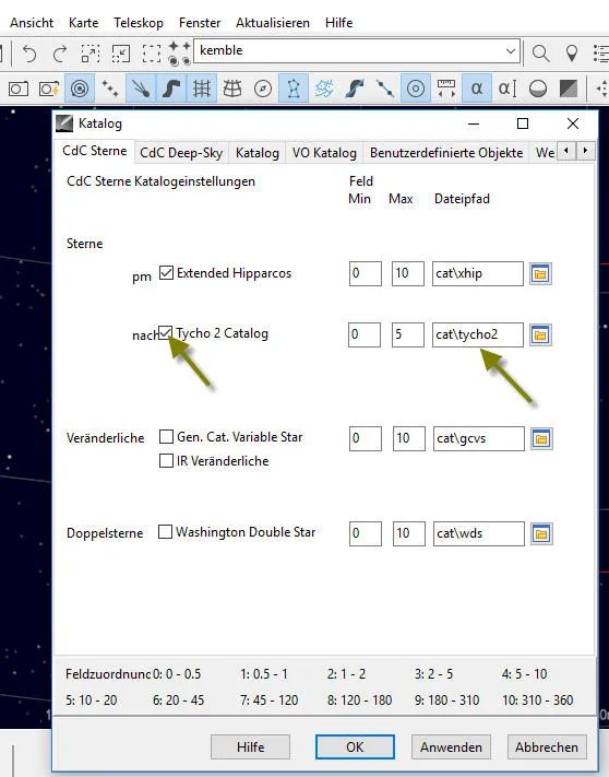
CdC Menüleiste -> Einstellungen ->  Katalog -> CdC Sterne -> Sterne -> Hacken in Kästchen Tycho2 Catalog -> eintragen in Feld Dateipfad: “cat\tycho2”

Abbildung 2: Cartes du Ciel: Einstellungen – Katalog  (Google Drive: Cartes-du-Ciel-22.jpg)


Cartes du Ciel: Katalog Tycho 2

Damit das so geht, müssen natürlich zunächst die entsprechenden Katalog-Dateien auf dem Computer vorhanden sein. Ich wollte z.B. Objekte aus dem Sharpless-Katalog anzeigen lassen. Das SH2-Feld im Reiter “CdC Deep Sky” bei Cartes du Ciel wurde aber rot, wohl weil unter cat\sh2 keine Katalog-Dateien installiert waren.

Also zuerst die Katalog-Daten holen z.B. bei SourceForge von:
https://downloads.sourceforge.net/project/skychart/2-catalogs/Nebulea/skychart-data-dso-4.0-3431-windows.exe

Sternkarten ausdrucken

Es können mehrere Sternkarten definiert, gespeichert und gedruckt werden:    sehr gut

Das Drucken von Sternkarten geht bei Cartes du Ciel ganz einfach:

  • Wir positionieren die CdC-Anzeige auf einen Himmelsausschnitt (siehe “Navigation”).
  • Mit Menü -> Datei -> Seitenansicht können wir kontrollieren, ob der Himmelsausschnitt so wie beabsichtigt ist
  • Bei Menü -> Datei -> Drucker einrichten könen wir noch Hoch- oder Querformat einstellen
  • Am besten speichern wir den eingestellten Himmelsausschnitt mit: Menü -> Datei -> Karte speichern
  • Dann wird mit Menü -> Datei -> Drucken der Druck des Himmelsausschnittes als Sternkarte gestartet (evtl. noch als PDF drucken)

Horizontdatei

Der Horizot wird eingeblendet durch:  Einstellungen -> Beobachtungsort -> Horizont

Eine Horizontdatei ist eine Textdatei, die für jedes Azimut die Höhe des lokalen Horizonts angibt. Daraus bildet Cartes du Ciel einen Polygonzug.

Format der Horizontdatei:

Pro Zeile wird mit aufsteigendem Azimut (beginnend bei 0 als Norden) als Zahlenpaar Azimut und Höhe angegeben, wobei Kommentarzeilen mit “#” beginnen.

Beispiel:

# Horizont auf der Terasse in Eimsbuettel
00 25
05 27
24 30
64 29
82 24
103 28
120 30
135 30
138 30
150 80
180 85
200 85
220 85
240 85
250 85
270 85
290 80
300 80
306 30
309 30
322 30
332 27
351 22
360 25

Speicherort einer Horizontdatei

Gespeichert werden die Horizontdateien im Ordner: d:\bin\Ciel\data\horizon

Wobei d:\bin\Ciel bei mir der Installationsordner von Cartes du Ciel ist.
Um die Horizontdatei im o.g. Ordner abzuspeichern müssen natürlich die passenden Schreib-/Lese-Rechte vorhanden sein, was in neueren Windows-Versionen manchmal merkwürdig sein kann.

Einstellen einer Horizontdatei

Für jeden Beobachtungsort kann eine Horizontdatei eingestellt werden: Menü -> Einstellungen -> Beobachtungsort -> Horizont

Teleskopsteuerung

Verbindung von Montierung zum Computer

Zur Steuerung der Montierung und damit des Teleskops muss die Montierung in geeigneter Weise mit dem Computer verbunden werden, auf dem dann die Software Cartes du Ciel läuft.

Wie eine solche Verbindung hergestellt wird, kann von Montierung zu Montierung unterschiedlich sein und ich habe das in den jeweiligen Artikeln über die spezifische Montierung beschrieben:

Teleskopsteuerung mit Cartes du Ciel

Wenn ich nun mit Cartes du Ciel mein Teleskop steueren will, muss ich nachdem die Verbindung hergestellt wude (s.o.) einige Einstellungen in Cartes du Ciel vornehmen.

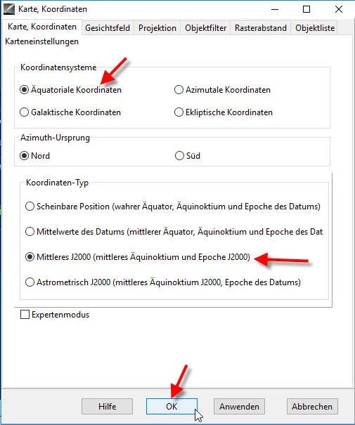
Äquinoktikum 2000.0 einstellen

Das Äquinoktikum (J2000) muss in Cartes du Ciel und im ASCOM-Treiber korrekt und identisch eingestellt sein:

Bei Cartes du Ciel einstellen:  Menü -> Einstellungen -> Karte, Koordinaten…

Bildbeschreibung: CdC Menüleiste –> Einstellungen –> Karte, Koordinaten –> Koordinatensystem: Radiobutton “Äquatoriale Koordinaten” & Koordinaten-Typ Radiobutton ” Mittleres J2000 (…)” & Schaltfläche “OK”

Abbildung 3: Cartes du Ciel: Koordinaten (Google Drive: Cartes-du-Ciel-11.jpg)


Cartes du Ciel: Epoche J2000

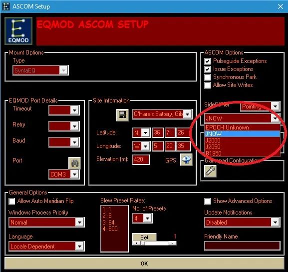
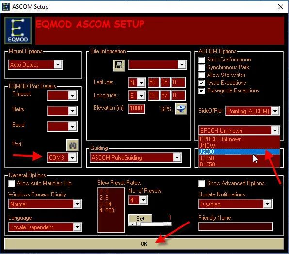
Das gleiche Äquinoktikum (J2000) im ASCOM-Treiber: einstellen; z.B. EQMOD  ASCOM SETUP

Abbildung 4: ASCOM SETUP -> Drop-Down “Epoch”: J2000  & Schaltfläche “OK” (Google Drive: Cartes-du-Ciel-12.jpg)


Cartes du Ciel: Epoche J2000 in EQMOD

 Im EQMOD ASCOM Setup einstellen:

  • Epoche : J2000
  • EQMOD Port Details: Port COMx (wie im Windows Gerätemanager erkannt)
  • Schaltfläche “OK”

Teleskop-Verbindung: Erster Schritt in CdC
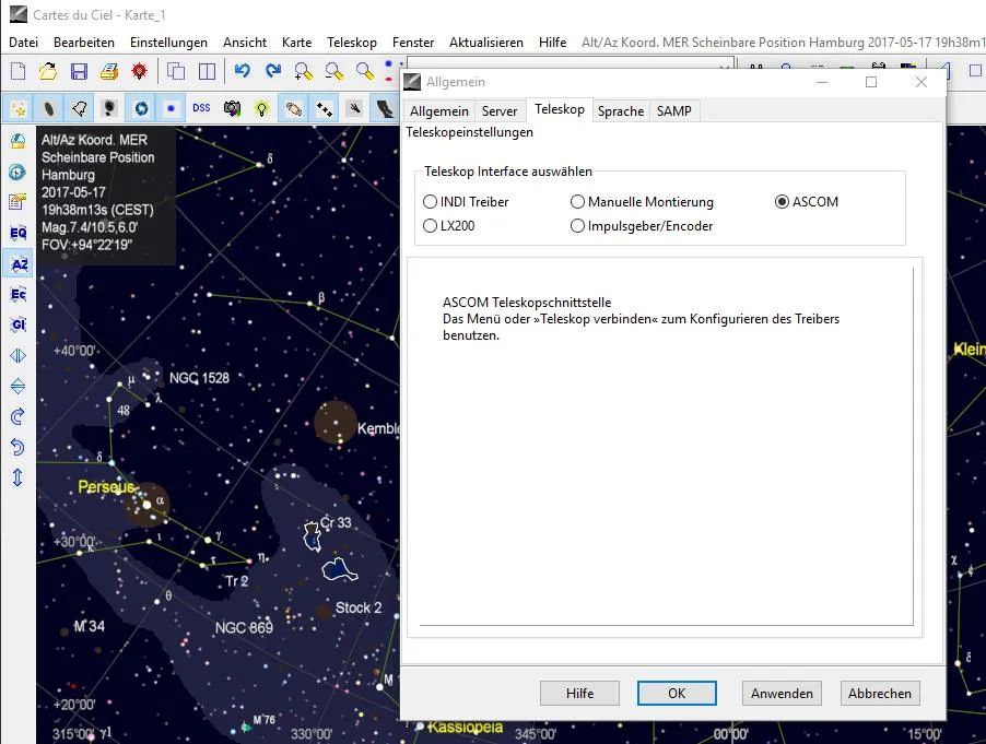
Als Interface “ASCOM” auswählen: Menü -> Teleskop -> Teleskopeinstellungen…

Beschreibung:  CdC Menüleiste –> Teleskop –> Teleskopeinstellungen –> Reiter “Teleskop” –> Teleskop Interface auswählen: Radio-Button “ASCOM”

Abbildung 5: Cartes du Ciel -> Teleskopenstellungen (Google Drive: CdC-01.jpg)


Cartes du Ciel: Teleskopsteuerung über ASCOM

Teleskop-Verbindung: Zweiter Schritt in CdC

Menü -> Teleskop -> Teleskop verbinden…

Das sieht je nach Teleskop leicht anders aus.

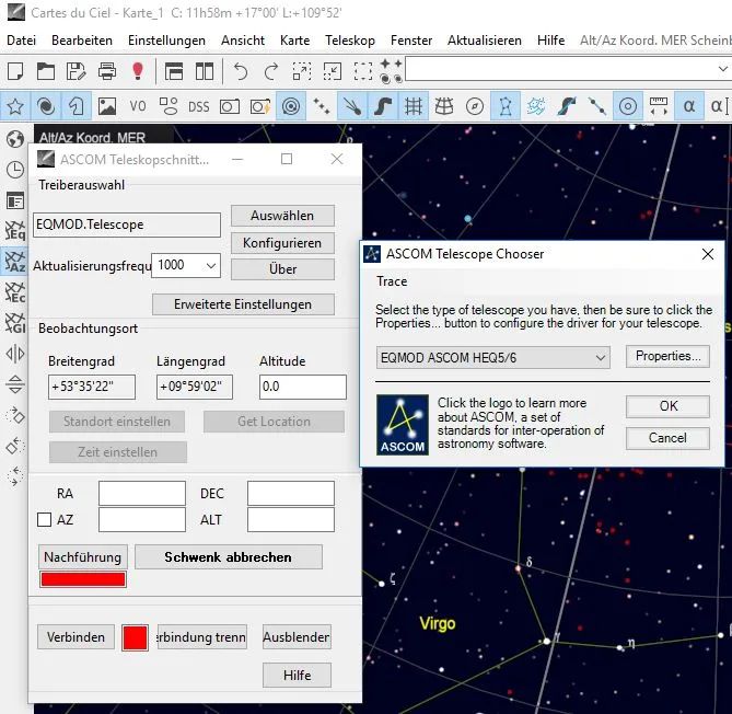
Variante 1 “HEQ5 Pro mit ASCOM-Treiber EQMOD”

Bildbeschreibung:

  • CdC Menüleiste –> Teleskop –> Teleskop verbinden –> Dialogbox “ASCOM Teleskopschnittselle: Schaltfläche “Auswählen”
    • Treiberauswahl “EQMOD.Telescope”
  • In der Dialogbox “ASCOM Telescope Chooser” –> Drop-Down “EQMOD ASCOM HEQ5/6”  & Schaltfläche “OK”
  • CdC Menüleiste –> Teleskop –> Teleskop verbinden –> Dialogbox “ASCOM Teleskopschnittstelle”:
    • Treiberauswahl “EQMOD.Telescope” & Schaltfläche “Konfigurieren”
    • Dialogbox: EQMOD ASCOM Setup (wie oben): COM-Schnittstelle einstellen und Schaltfläche “OK”

Abbildung 6: Cartes du Ciel: Teleskopschnittstelle (Google Drive: Cartes-du-Ciel-01.jpg)


Cartes du Ciel: Teleskop verbinden

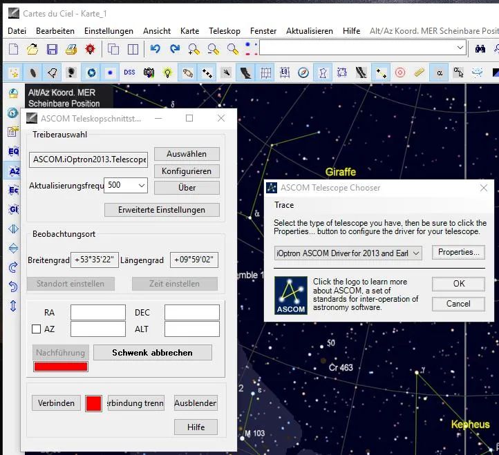
Variante 2: iOptron SmartEQ Pro mit ASCOM-Treiber von iOptron

Bildbeschreibung:

  • CdC Menüleiste –> Teleskop –> Teleskop verbinden  –> Schaltfläche “Auswählen”
    • ASCOM Telescope Choose
  • CdC Menüleiste –> Teleskop –> Teleskop verbinden  –> Schaltfläche “Konfigurieren”

Abbildung 7: Cartes du Ciel -> ASCOM Teleskopschnittstelle (Google Drive: CdC-03.jpg)


Cartes du Ciel: ASCOM Teleskop Chooser

Variante 3: Astro-Physics mit ASCOM-Treiber

Für Astro-Physics-Montierungen gibt es einen spezifischen ASCOM-Treiber.

Variante 4: FS-2-Steuerung mit ASCOM-Treiber

Falls man eine Montierung mit FS-2 Steuerung hat, geht man über “POTH

Funktionen der Teleskopsteuerung in CdC: Goto

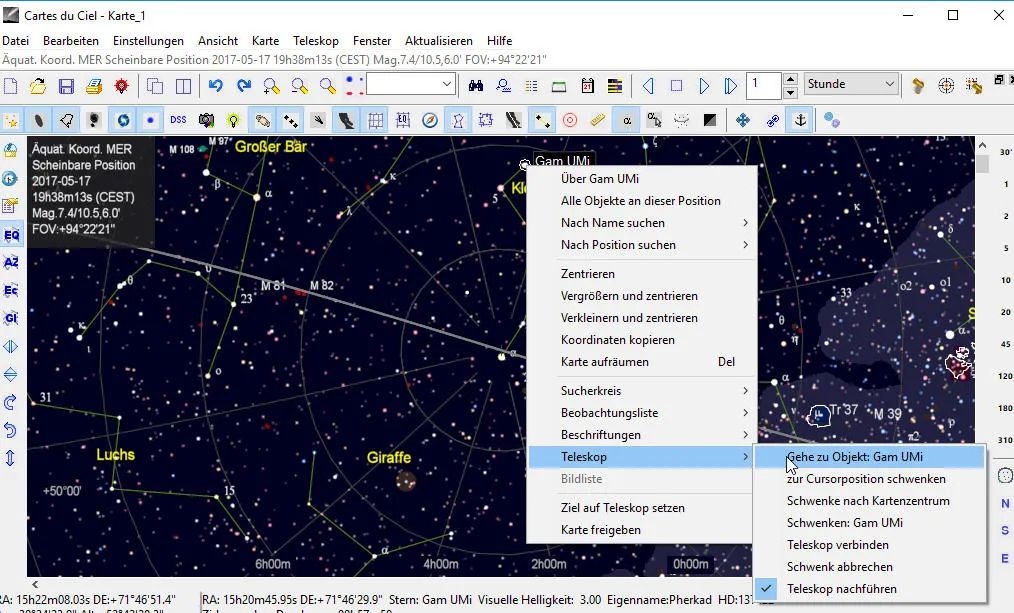
Die Hauptfunktion der Teleskopsteuerung ist das sog. “Goto”. Dazu selektiert man auf der von CdC angezeigten Sternkarte ein Objekt. Über das Kontextmenü (rechte Maustaste) kann man dann mit “Gehe zu Objekt <name>” klicken und das Teleskop sollte nun das Objekt anfahren (Goto)…

Abbildung 8: CdC Mit der Maus auf einen Stern (z.B. Gam UMi) zeigen und Rechtsklick -> Popup: “Teleskop” -> Popup: “Gehe zu Objekt Gam UMi” (Google Drive: CdC-04.jpg)


Cartes du Ciel: Telescope Goto

Voraussetzung für die Goto-Funktion ist, dass das Teleskop “weiss” wohin es am Anfang genau zeigt. Es ist also ein irgendwie geartetes “Goto Alignment” erforderlich. Dies kann ein klassisches 3-Star-Alignment mit der Handbox der Montierung sein, oder aber wir machen es über die Computersteuerung und nutzen dabei die SYNC-Funktion des EQMOD-Treibers.

Das klassische 3-Star-Alignment (auch Goto Alignment) wird mit der Handbox gemacht. Das kann ich nur mit einem guten Sucher-Fernrohr machen. Speziell der erste Schritt beim Goto-Alignment startet ja von einem nicht genau definierten Anfangspunkt, der “Home Position“, entsprechend ungenau ist das Goto auf den ersten Alignment-Stern. Diesen ersten Alignment-Stern  muss ich ja erst einmal am Himmel  identifizieren und dann ins Gesichtsfeld bekommen und ihn schließlich noch genau in die Mitte des Gesichtsfeldes einstellen. Das Gesichtsfeld mit einem APS-C-Sensor an meinem Teleskop Orion ED 80/600 ist: 2,2° x 1,5°

Funktionen der Teleskopsteuerung in CdC: SYNC

Für meine Montierung HEQ5 Pro wird eine SYNC-Funktion durch den EQMOD-Treiber ermöglicht. Voraussetzung für ein SYNC ist

  1. Ich bin mit Goto auf das Objekt gefahren
  2. Ich habe es mit den Steuerungstasten in die Mitte des Gesichtsfeldes (z.B. der angeschlossenen DLSR mit 10-fach Zoom) eingestellt.

Dann kann ich in der Software Cartes du Ciel auf SYNC drücken.

Beispiel

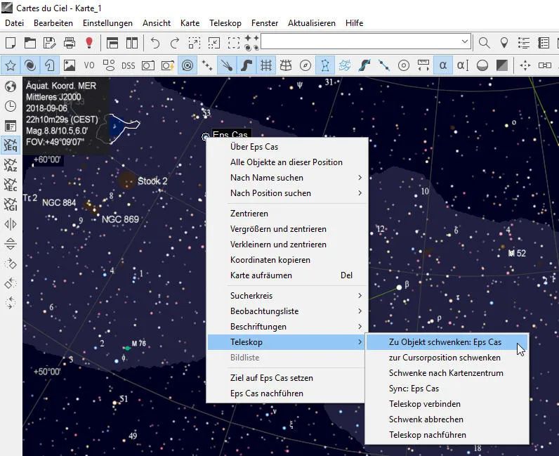
Also erst ein Goto auf Epsilon Cas: Klick mit rechter Maustaste auf Eps Cas

Abbildung 9: CdC Mausklick rechts auf einen Stern (z.B. Eps Cas) -> Popup “Teleskop” -> Popup “Zu Objekt schwenken Eps Cas” (Google Drive: Cartes-du-Ciel-20.jpg)


Cartes du Ciel: Goto Eps Cas

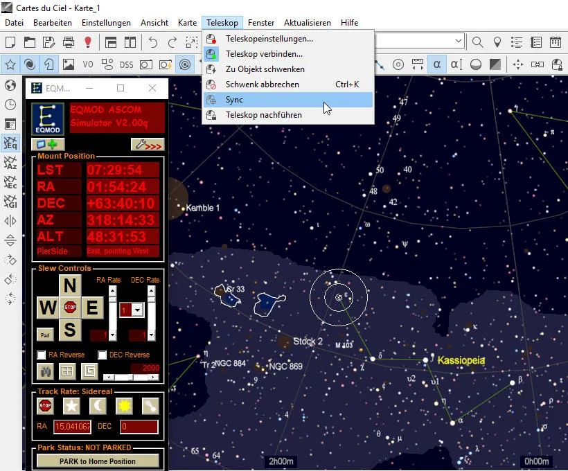
Dann ein Sync auf Epsilon Cas: Menü -> Teleskop -> Sync

Abbildung 10: CdC Menüleiste –> Teleskop –> Drop-Down: “Sync” (Google Drive: Cartes-du-Ciel-13.jpg)


Cartes du Ciel: Telescope Sync

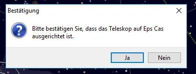
Dann eine Bestätigung, dass das Teleskop auch tatsächlich – ggf. nach manuelle Feinkorrektur –  auf Epsilon Cas zeigt
Wenn diese Aufforderung zu Bestätigung kommt, weiss man, dass wirklich ein SYNC durchgeführt wird. Manchmal sind nämlich die Übersetzungen ind Deutsche etwas merkwürdig, sodass man den SYNC-Befehl nicht auf Anhieb findet.

Abbildung 11: Dialogbox “Bestätigung” -> Bitte bestätigen Sie, dass das Teleskop auf Eps Cas ausgerichtet ist. -> Schaltfläche “Ja” (Google Drive: Cartes-du-Ciel-14.jpg)


Cartes du Ciel Bestätigung Eps Cas Sync

Nun erst wird der SYNC wirklich gemacht.

Alignment Points / Pointing Model

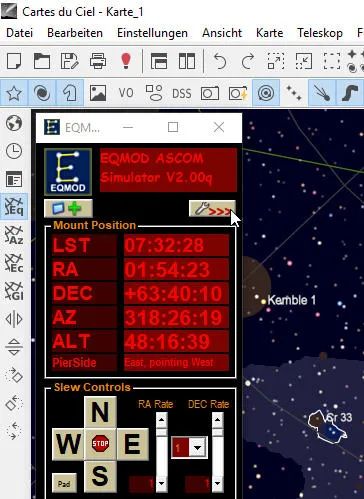
Im EQMOD-Treiber kann ich mir jetzt den (die) gesetzten Alignment-Point(s) anzeigen lassen:  EQMOD “aufklappen” (Schaltfläche  “>>>”):

Abbildung 12: EQMOD-Fenster: Schaltfläche “Schraubenschlüssel >>>” klicken (Google Drive: Cartes-du-Ciel-15.jpg)


Cartes du Ciel: EQMOD Alignment Points

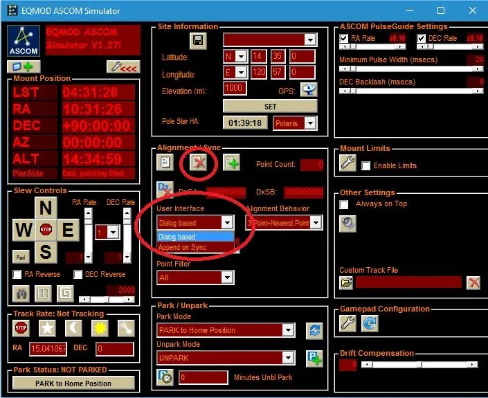
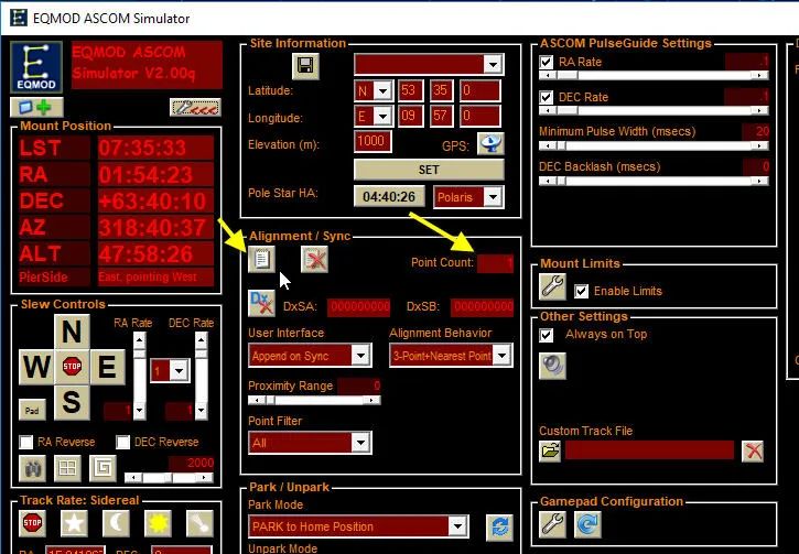
Dann sieht man im nach rechts aufklappenden erweiterten EQMOD-Fenster im Bereich “Alignment / Sync” unter “Point Count” (rechter Pfeil) die Anzahl der gesetzten Alignment-Points und man kann sich durch klicken auf “Point List” (linker Pfeil) die Liste der Alignment-Points im Detail anzeigen lassen.

Abbildung 13: EQMOD Alignment/Sync (Google Drive: Cartes-du-Ciel-16.jpg)


Cartes du Ciel: EQMOD Alignment/Sync

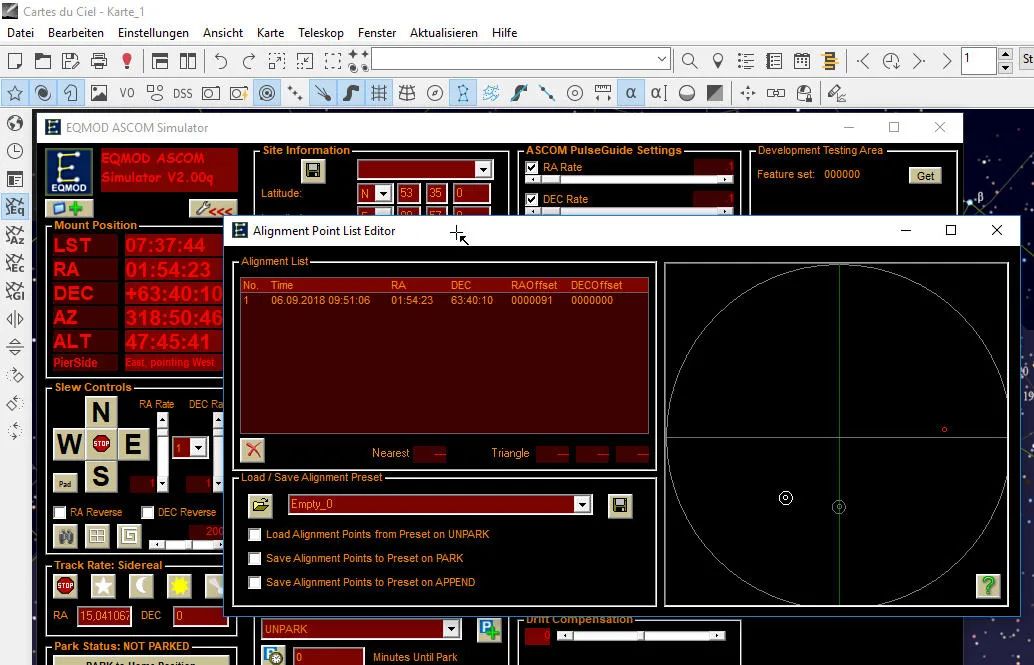
Liste der Alignment Points im Detail:

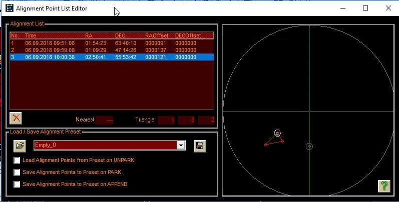
Abbildung 14: EQMOD erweiteres Setup -> Im Bereich “Alignment/Sync” klicken auf die kleine Schaltfläche, die wie ein Notizblock aussieht (Google Drive: EQMOD_ASCOM_Alignment_List.jpg)


Cartes du Ciel: EQMOD Alignment/Sync

Ich habe dann noch weitere Sterne (in meinem begrenzten Himmelsausschnitt) angefahren und darauf weitere Alignment Points gesetzt: Eta Per und Phi And

Abbildung 15: EQMOD erweiteres Setup -> Im Bereich “Alignment/Sync” klicken auf die kleine Schaltfläche, die wie ein Notizblock aussieht (Google Drive: Cartes-du-Ciel-18.jpg)


EQMOD: Alignment Point List Editor

Diese Art des Goto Alignments (also mit SYNC über Software) wird speziell durch den EQMOD-Treiber ermöglicht. Wenn man das nutzen möchte, ist es also empfehlenswert, sich eine Montierung auszusuchen, die EQMOD kann (z.B. die Sykwatcher HEQ5 Pro).

Die SYNC-Funktion setzt voraus, dass das Gesichtsfeld meines Teleskops auf ein bekanntes Objekt mittig positioniert wird. Die genauen Himmels-Koordinaten sind damit bekannt. Himmels-Koordinaten und aktuelle Position des Teleskops fliessen dann in den weiteren Goto-Algorithmus des EQMOD (Pointing Modell) ein.

Statt eines “bekannten” Himmelsobjekts kann ich auch einfach mit dem Teleskop irgendwohin zeigen, ein Foto schießen und darauf ein Plate Solving anwenden – dann muss ich keinerlei Feinausrichtung im Gesichtfeld vornehmen und kann sofort ein SYNC machen – denn das Teleskop zeigt ja (noch immer) dahin, wo das Foto geschossen wurde und dessen Himmelskoordinaten (Bildmitte) das Plate Solving gerade ermittelt hat. Für diese komfortable Vorgehensweise beim Goto Alignment muss meine Software dann neben der Teleskopsteuerung auch noch die Kamera-Steuerung (Capture) und ein Plate Solving ermöglichen. Das mache ich beispielsweise mit der Software APT.

Zur Zeit verwende ich CdC und APT in Kombination: Goto mache ich gerne mit CdC, Plate Solving und Sync mit APT…

Astronomie: Planetarium-Software “Stellarium”

Gehört zu: Astro-Software
Siehe auch: Stellarium Horizontbilder, Stellarium Skripts, Beobachtungsplanung, Planetarium-Software, Cartes du Ciel, Guide, SkySafari, N.I.N.A.
Benutzt: Fotos aus Google Drive

Stand: 09.01.2024

Die Planetarium-Software “Stellarium”

Stellarium gehört zu der Gattung “Planetarium-Software” und ist auf Windows-Plattformen sehr verbreitet und wird gerne zur Beobachtungsplanung verwendet. Weitere sehr bekannte Planetariumsprogramme für Windows sind: Cartes du Ciel und Guide sowie SkySafari auf iOS und Android.

Einige spezielle Funktionen von Stellarium habe ich separat beschrieben:

Ich benutze Stellarium für folgende Einsatzgebiete:

  • Orientierung am Sternenhimmen beispielsweise im Urlaub in fremden Gegenden
  • Orientierung am Sternenhimmel für andere Zeitpunkte als “jetzt” (Planung für die Zukunft und Analysen der Vergangenheit)
  • Wo stehen Erdsatelliten, Kometen etc.
  • Planung Astrofotografie: Brennweite und Bildausschnitt (Framing)
  • Planung Astronomie: Horizontsicht
  • Steuerung meiner Montierung Skywatcher HEQ5 Pro über ASCOM (Goto)
  • Nicht SYNC, das mache ich innerhalb meiner Aufnahme-Software. Dort mache ich immer Platesolve und SYNC zusammen); beispielsweise mit APT oder N.I.N.A.

Ich komme mit “Stellarium” auf meinem Windows-Notebook sehr gut zurecht.

Stellarium benötigt für die schöne Darstellung des Nachthimmels sehr spezielle Funktionen der Grafikkarte im Computer.

Stellarium benutzt dazu OpenGL, was seinerseits die Treiber der Grafikkarte benutzt. Die Grafikkarte mit ihren Treibern muss deswegen einigermassen performant sein und nicht zu alt. Falls die Grafikanzeige auf diese Art und Weise nicht richtig läuft, kann alternativ eine Stellarium-Version benutzt werden, die ANGLE verwendet, was dann zum Steueren der Grafik DirectX benutzt.

Stellarium wird deswegen seit einiger Zeit standardmäßig in zwei Versionen bereitgestellt:

  • Normal-Version d.h. mit OpenGL
  • ANGLE-Version d.h. mit DirectX

Stellarium Konfigurationsdateien

Generelles: C:/Users/<userid>/AppData/Roaming/Stellarium/data/ssystem.ini

Standorte:  C:/Users/<userid>/AppData/Roaming/Stellarium/data/user_locations.txt

Landschaften:  <Stellarium-Ordner>/landscapes/<landscape ID>

Okulare:  C:/Users/<userid>/AppData/Roaming/Stellarium/modules/oculars/ocular.ini

Skripts:   <Stellarium-Ordner>/Scripts

Vertiefende Artikel zu Stellarium

Installation auf meinem Windows-Computer Acerbaer

  • Definitive Software Library ID: Stellarium
  • Name: Stellarium
  • Version: 0.22.2   (Jul. 2022)
  • Hersteller/Bezugsquelle: http://www.stellarium.org/de/
  • Funktion: Astronomie
  • Betriebssystem: Windows, Linux, Android,…
  • Installations-Ordner: C:/Program Files/Stellarium
  • Daten-Ordner: C:/Data/Stellarium
  • Lizenz: kostenlos

Stellarium Versionen

Mit Stellarium 0.15.2 konnte ich schnell und bequem astronomische Beobachtungen planen. Stellarium wird laufend weiterentwickelt und mittlerweile bin ich auf Version 0.22.2 gelandet.

  • 2016-07-31 Version 0.15.0
  • 2017-06-21 Version 0.16.0
  • 2017-12-21 Version 0.17.0    Based on Qt 5.9.3, INDI Support für Teleskopsteuerung
  • 2018-03-25 Version 0.18.0
  • 2019-12-22 Version 0.19.3    Teleskopsteuerung endlich über ASCOM
  • 2020-03-29 Version 0.20.0
  • 2020-04-20 Version 0.20.1
  • 2020-06-22 Version 0.20.2
  • 2020-09-27 Version 0.20.3    Win 64 Bit
  • 2020-12-28 Version 0.20.4
  • 2021-03-29 Version 0.21.0
  • 2021-06-24 Version 0.21.1
  • 2021-09-27 Version 0.21.2  Observation Lists (statt Bookmarks)
  • 2021-12-25 Version 0.21.3
  • 2022-03-27 Version 0.22.0
  • 2022-04-16 Version 0.22.1
  • 2022-07-07 Version 0.22.2
  • 2022-10-01 Version 1.0       Based on Qt 6
  • 2022.10-31 Version 1.1        Support OpenGL 3.3 Core profile
  • 2022-12-25 Version 1.2       Improved rendering of Milkyway, Zodiacal Light and Landscapes
  • 2023-09-25 Version 23.3

Dokumentation

Links:

Zukunftssicherheit

  • Es gibt Versionen für Windows, Mac OS und Linux
  • Projektleiter: Fabien Chéreau
  • Per 25.09.2023 ist die aktuelle Version 23.3
  • sehr aktive Weiterentwicklung

Installationsschritte

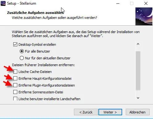
Wenn man eine neue Version von Stellarium installiert, können die bisher gemachten Einstellungen (z.B. Okulare, Sensoren, Teleskope, Skripte) verloren gehen. Wenn man solche “alten” Einstellungen behalten will, muss man bei der Installation darauf achten, dass bei “Dateien früherer Installationen entfernen” nichts angehakt ist; z.B. “Entferne Plugin-Konfigurationsdatei” etc.

Abbildung 1: Stellarium Installation (Google Drive: Stellarium03.jpg)

Funktionen von Stellarium

Stellarium als “Planetariumsprogramm” in N.I.N.A.

Wenn Stellarium bei N.I.N.A. als sog. “Planetariumsprogramm” angegeben wird, muss in Stellarium im “Einstellungsfenster [F2]” die Erweiterung “Fernbedinung” geladen und aktiviert werden. Als Port-Nummer nehmen wir den voreingestellten Wert 8090.

Wir können dann in Stellarium ein Ziel-Objekt aussuchen und dessen Ziel-Koordinaten in N.I.N.A. übernehmen.

Beobachtungsort einstellen

  • Beobachtungsort einstellen: gut
  • Seit Version 0.15.2 kann man jedem Beobachtungsort auch eine Zeitzone zuordnen

Gespeichert wird das in der Datei user_locations.txt. Im Ordner: D:\Users\<userid>\AppData\Roaming\Stellarium\data

Beobachtungszeit und -datum einstellen

  • Beobachtungszeit und -datum einstellen: gut

Navigieren und orientieren am (virtuellen) Sternenhimmel

  • Zoomen (FoV): Gut, mit dem Mausrad
  • Positionieren: Gut, per “Drag and Drop”
  • Einblenden Koordinatennetze horizontal & äquatorial: gut
  • Einblenden von Sternnamen und DSO-Namen: gut

Welche Himmelsbjekte soll Stellarium angezeigen?

Sterne

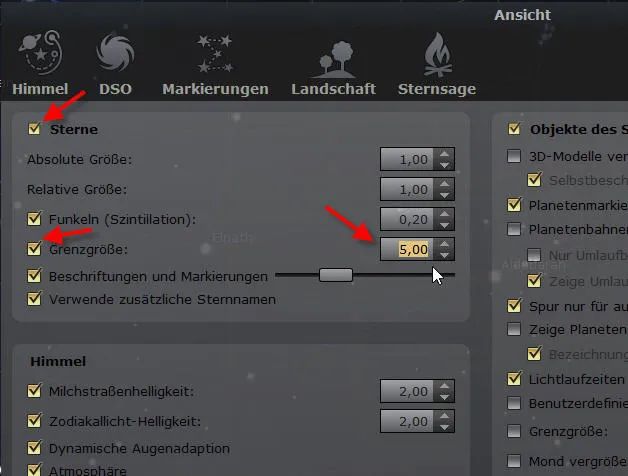
Die Fixsterne aus einem Katalog (s.u.) bis zu einer einzustellenden Grenzgröße

Abbildung 2: Stellarium -> Ansicht (F4) -> Himmel -> Sterne (Google Drive: Stellarium01-1.jpg )

Erdsatelliten

Um Erdsatelliten in Stellarium anzuzeigen, muß man die Erweiterung “Satelliten” benutzen:

  • Einstellungsfenster [F2] -> Konfiguration -> Erweiterungen
  • Satelliten-Konfiguration

Kometen

Um Kometen in Stellarium anzuzeigen, muss man im Sonnensystem-Editor die Bahnelemente importieren:

  • Einstellungsfenster [F2]-> Konfiguration -> Erweiterungen
  • Sonnensystem-Editor –> Konfigurieren -> Sonnensystem
    • Neuen Himmelskörper hinzufügen
    • Bahnelemente im MPC-Format importieren…
    • Listen: Kometen
    • Onlinesuche: da ist eine genaue Schreibweise erforderlich z.B. “C/2015 V2” nicht “C/2015 v2”

Bei Wechsel des Computers möchte man das alles vielleicht mitnehmen. Es steht standardmäßig in der Datei: C:/Users/<userid>/AppData/Roaming/Stellarium/data/ssystem.ini

Meteorstöme

Um Meteorströme in Stellarium anzuzeigen, mass man die Erweiterung “Meteorschauer” aktivieren:

  • Einstellungsfenster [F2] ->Konfiguration -> Reiter “Erweiterungen”
  • Meteorschauer -> konfigurieren

Dann “Himmel- und Anzeigeoptionsfenster [F4]” –> Himmel –> Sternschnuppen –> ZHR

Suchen von Beobachtungsobjekten

Suchbegriff kann der Name oder die Koordinaten sein: gut

Winkelabstände messen

  • gut
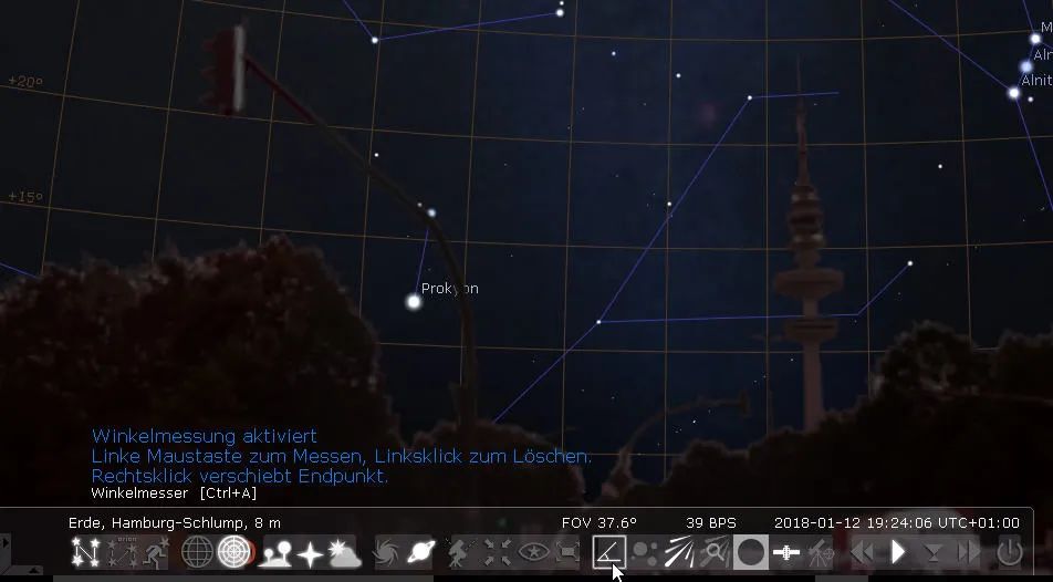
    • Linkes Menü -> Einstellungsfenster -> Reiter “Erweiterungen” -> Winkelmesser -> Beim Start laden (Aufruf in unterer Menüleiste)

Abbildung 3: Stellarium Winkelabstände messen (Google Drive: Stellarium01-2.jpg)

Gesichtsfeld-Rahmen (Sensorfeld bzw. Okular)

  • Arbeitsaufwendig
    • Linkes Menü -> Einstellungsfenster [F2] -> Reiter “Erweiterungen” -> Okulare (Aufruf mit Alt-O)

Einmalaufwand: Definition der Teleskope und Sensoren

Gespeichert werden diese Einstellungen in der Datei:

C:/Users/<userid>/AppData/Roaming/Stellarium/modules/oculars/ocular.ini

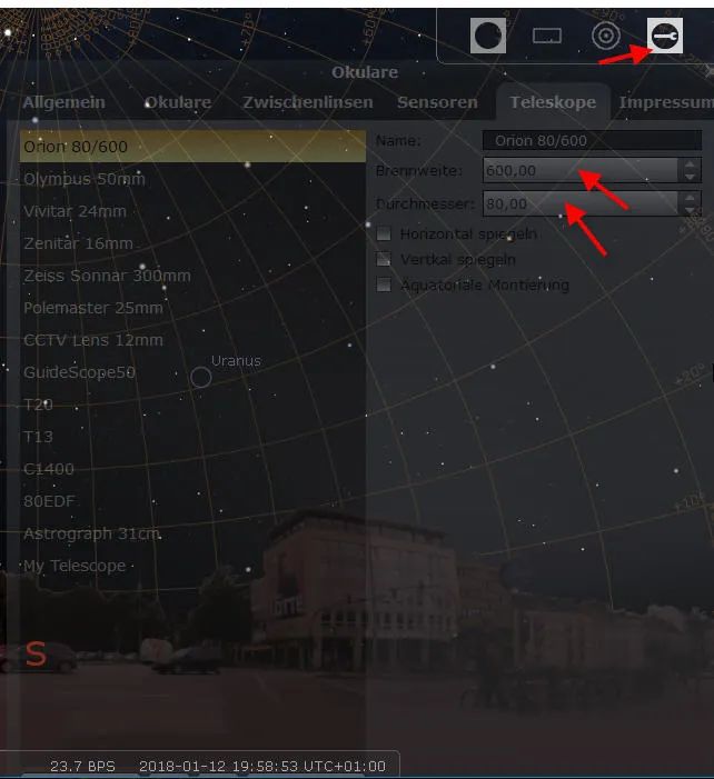
Abbildung 4: Stellarium Gesichtsfeld: Welches Teleskop (Google Drive: Stellarium02-2.jpg)

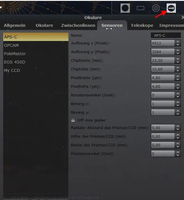
Abbildung 5: Einmalaufwand: Definition der Sensoren (Google Drive: Stellarium02-3.jpg)

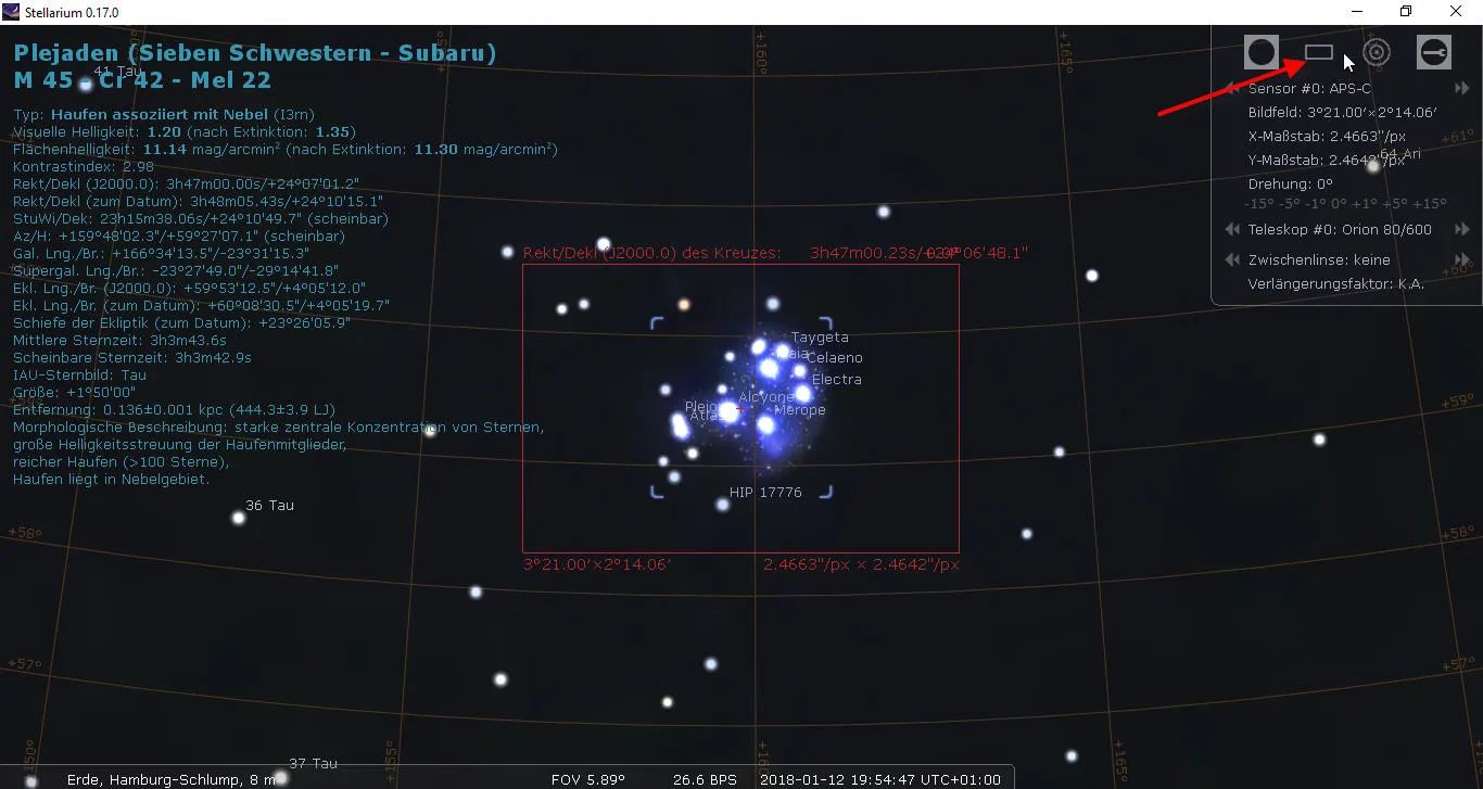
Abbildung 6: Auswählen und Anzeige eines Gesichtsfeldes am Himmel (Google Drive: Stellarium02-1.jpg)


Liste von Beobachtungsobjekten

  • NEIN    …  ab der Version 0.21.2 gibt es sog. “Observation Lists”

Beobachtungskalender

Was kann ich heute sehen?

Sternkataloge einbinden

Geht wie folgt (aber welche Kataloge lädt Stellarium denn ganz genau?)

  • Linkes Menü -> Einstellungsfenster [F2] -> Reiter “Werkzeuge” -> Sternkatalog Aktualisierungen
  • Die nachgeladenen Sterne werden erst nach einem Neustart von Stellarium sichtbar
  • About 99% of all these stars come from the NOMAD catalog (Naval Observatory Merged Astrometric Dataset version 1, by USNO). The rest (brighter ones) from Tycho2 and Hipparcos.

Stellarium speichert dies in der Datei starsConfig.json im Ordner D:\Users\<userid>\AppData\Roaming\Stellarium\stars\default

Sternkarten ausdrucken

Zielkoordinaten für N.I.N.A.

Wenn ich in Stellarium ein Objekt (z.B. Stern) mit einem Mausklick selektiere, können die Koordinaten dieses Objekts von z.B. N.I.N.A. ausgelesen und verwendet werden.

Dazu muss ich in Stellarium den “Server” einstellen. Dazu aktiviere ich die Stellarium-Erweiterung “Fernbedienung” und setze beim Konfigurieren die Häckchen auf: “Server aktiviert” und “Automatisch beim Start aktivieren”. Die Port-Nummer lasse ich auf 8090.

In N.I.N.A. muss ich dann Stellarium als Planetariumsprogramm konfigurieren. Wie das geht, habe ich in meinem NINA-Blog beschrieben.

Teleskop-Steuerung per Computer

Mit der Software Stellarium kann ich meine Goto-fähige Montierung statt über die Handbox auch über meinen Windows-Computer steuern. Dafür muss die spezielle Montierung in geeigneter Weise mit dem Windows-Computer verbunden werden: Siehe dazu: Teleskop-Steuerung per Computer

Die weitere Vorgehensweise mit Stellarium habe ich ein einem separaten Artikel beschrieben.

Benutzeroberfläche

intuitiv, gut

Landscapes / tatsächlicher Horizont / Kimm

Für die Beobachtungsplanung an einem bestimmten Ort, ist es sehr hilfreich, wenn der “tatsächliche” Horizot (Bäume, Häuser etc.) angezeigt werden kann.

In Stellarium heisst das Thema “Landscapes”, was ich in einem gesonderten Blog-Artikel beschrieben habe.

Scripting mit Stellarium

Zum Thema “Stellarium Scripts” habe ich einen eigenen Blog-Artikel geschrieben.


Astrofotografie und DeepSkyStacker DSS

Gehört zu: Astro-Software
Siehe auch: Bildbearbeitung  (Image Processing), Stacking (Calibration), Astro Pixel Processor, Belichtungszeiten
Benutzt: Fotos von Google Archiv

Stand: 01.10.2022

Warum DeepSkyStacker?

Die kostenfreie Software DeepSkyStacker “DSS” ist die beliebteste Software zum “Stacken” einzelner Astro-Bilder.

Bezugsquelle: http://deepskystacker.free.fr/german/

Versionen:

  • 4.1.1 Okt. 2018
  • 4.2.2 Aug 2019   LibRaw statt DCRaw
  • 4.2.1 Juli 2019
  • 4.2.3 Jan 2020
  • 4.2.4 Aug 2020  LibRaw updated to 0.20 providing support for over 1300 cameras including Canon Eos R (.CR3 files). CR3 file extension added to list of raw file types.
  • 4.2.5 Aug 2020
  • 4.2.6 Mai 2021  Upgrade to LibRaw snapshot 202101 (new camera support)

Stacken bedeutet, dass man mehrere Bilder von seinem Himmelsobjekt macht (mit unveränderter Einstellung und aktivierter Nachführung). Diese Bilder werden an per Software (z.B. DSS) übereinandergelegt (= “gestackt”), wobei Addition oder Mittelwert zum gleichen Ergebnis führen, wenn der Zahlenraum, in dem man rechnet, groß genug ist, damit keine Helligkeitswerte “abgeschnitten” werden. Bei 32-Bit-Software ist das sicher gegeben.

Intuitiv denkt man vielleicht, man sammelt mehr Licht, in Wirklichkeit ist es das Hintergrundrauschen was gemittelt wird und so gedämpft wird und damit hebt sich das Nutzsignal sich besser aus dem Hintergrundrauschen ab. Der Fachmann spricht vom SNR Signal-Noise-Ratio.

Ausser Deep Sky Stacker kann man auch andere Software zum Stacken verwenden; z.B.

Contine reading

Astrofotografie: Bildbearbeitung mit GIMP

Gehört zu: Astro-Software
Siehe auch: Bildverarbeitung (Image post processing)

Bildbearbeitung mit GIMP – Postprocessing

GIMP ist ein kostenloses Programm zur Bildbearbeitung (pixelbasiert) und leistet in etwa dasselbe wie Adobe Photoshop (z.B. Ebenen, Journal,…), eben nur kostenlos.

GIMP bedeutet: “GNU Image Manipulation Program” und ist Open Source.

Seit der Version 2.9.2 (27. Nov 2015) unterstützt GIMP auch 16-Bit-Formate; d.h. 16 Bit Farbtiefe pro Farbkanal.

Es ist also sinnvoll, bestimmte Bildbearbeitung von Astrofotos z.B. das Stretchen in GIMP zu machen, weil es vor dem Stretchen auf die Farbtiefe ankommt.

Installation von GIMP

Download-Link: https://www.gimp.org/downloads/

Version: 2.10.6 (19. Aug 2018)

Version: 2.10.24 (28. Mar 2021)

Reihenfolge bei der Bildbearbeitung

Zuerst die Einzelaufnahmen stacken z.B. mit Deep Sky Stacker “DSS”

Dann in Fitswork:

  • Ränder beschneiden
  • Histogramm ein bisschen stretchen
  • Hintergrund ebnen (Nebel) – Vignettierung entfernen
  • Farben korrigieren (Rechte Mastaste, Umgebung als Grauwert)
  • Speichern als 16-Bit-TIFF

Schließlich mit GIMP

  • TIFF-Datei öffnen
  • Histogram stretchen: Farben, Werte
  • Gamma anpassen: Faben, Kurven
  • Farbrauschen entfernen
  • Speichern als TIFF

GIMP Funktionen

GIMP Histogramm

Menü -> Farben -> Werte

GIMP Gradationskurve

Menü -> Farben -> Kurven

Damit kann man Punkte mit der Pipette markieren und solche Punkte z.B. unverändert lassen (z.B. heller Stern) und andere Punkte “hochziehen” (z.B. interessantes Detail) – sinnvoll wohl für das feine Stretchen von Nebeln, Polarlicht etc. (weniger für Sterne???).

GIMP Journal

Menü -> Fenster -> Andockbare Dialoge -> Journal

Damit kann man die Bearbeitungsschritte verfolgen und z.B. eine Vorher/Nachher-Kontolle durchführen

GIMP Plugins

Da soll es viele geben u.a. auch von Adobe Potoshop her…

GIMP Werkzeuge: Klonen / Heilen

Werkzeug im Werkzeugkasten auswählen. Dann mit Strg-Maus-Klick den zu kopierenden Bereich (Quelle) auswählen (es erscheint ein Fadenkreuz). Dann mit der Maus auf den Zielbereich klicken.

Achtung: es darf keine Auswahl aktiv sein.

Luminanzmaske

Quelle: https://www.youtube.com/watch?v=-nCzcK34twc

  1. Das Bild öffnen
  2. Bild als Ebene kopieren (damit wir das Originalbild nicht verändern)
  3. In Schwarz-Weiß-Bild umwandeln: Menü -> Farbe -> Entsättigen -> Entsättigen -> Modus=Leuchtkraft
  4. Helle Lichter auswählen in separate Kanäle:
    • Im Kanal-Dialog (die Kanäle “Rot”, “Grün”, “Blau” sind jetzt identisch, da Schwarz-Weiß)
    • Einen Kanal (z.B. Blau) in den unteren Bereich ziehen und den Namen “Lichter” geben
    • Menü -> Auswahl -> Alles (ergibt “maschierende Ameisen”)
    • Dann ggf. wiederholt:
      • rechte Maustaste auf den Kanal namens “Lichter” und “von Auswahl abziehen”
      • Menü -> Auswahl -> in Kanal speichern
      • dem neuen Kanal den Namen “Lichter 1” geben
      • Die letzten drei Schritte wiederholen. Dadurch vergrößert sich immer die Auswahl der Lichter ein wenig. Dabei immer den ersten Kanal namens “Lichter” abziehen und das Ergebnis als neuen Kanal namens “Lichter n” speichern
  5. Menü -> Auswahl -> Nichts

Astrofotografie: Liste meiner Astro-Software

Gehört zu: Astronomie
Siehe auch: N.I.N.A.

Stand: 2.8.2022

Liste meiner Astro-Software

Als Einsteiger in die Astrofotografie wird mir eine Menge Software zur Unterstützung empfohlen.

Ich beginne mit einer unsortierten Liste, die ich stückweise ausarbeiten will.

Versionsverfolgung

Allerdings will ich zu der häufig benutzten Software eine Versionsverfolgung vornehmen:

Software Aktuelle Version Installierte Version Bemerkung
Stellarium 0.22.2 (2022) 0.22.2 Goto gut mit ASCOM- Montierungen
APT v4.01  (2022) v4.01 (2022) Stellarium als Planetarium, SessionCraft
SharpCap 4.0.9478 Pro (2022) 4.0.9478  Pro Polar Alignment
EQMOD 200w (2021) 200w
ASCOM Plattform 6.6 SP1 (2022) 6.6 SP1
Native Treiber ASI294 MC Pro 3.17 3.17 ???
All Sky Plate Solver 1.4 1.4.5.11 lange keine neue Version
ASTAP Version 2022.06.14 Version 2022.06.14 Platesolving mit N.I.N.A.
N.I.N.A. 10 HF3 (2020)
N.I.N.A. 2.00 (5. June 2022) 2.00 (5. June 2022) Three Point Polar Alignment

Contine reading

Astrofotografie: ASCOM Plattform, ASCOM Treiber

Gehört zu: Astro-Software
Siehe auch: ASCOM-Treiber EQMOD, Cartes du Ciel, APT, SharpCap, N.I.N.A.
Benutzt: Fotos von Google Drive

Stand: 09.12.2022

Die ASCOM-Platform – ASCOM-Treiber

Die Idee von ASCOM ist, für diverse astronomische Geräte (z.B. Video-Kamera, Teleskop-Steuerung, Filterrad, Fokussierer,…) nicht die proprietären Windows-Treiber einzusetzen, sondern sog. ASCOM-Treiber zu verwenden, so dass eine Astro-Software auch “nur” ASCOM zu unterstützen braucht und nicht diverse herstellerabhängige Geräte. Voraussetzung für solche ASCOM-Treiber ist die Installation einer sog.  ASCOM-Platform.

Download und Installation der ASCOM-Platform

Download-Link:  http://ascom-standards.org/

Nach der Installation der ASCOM-Platform hat man drei neue Programme:

  • Profile Explorer  (damit können die mit der ASCOM-Platform verbundenen Geräte angezeigt werden)
  • ASCOM Diagnostics    (damit können Verbindungen zu ASCOM-Geräten aufgebaut und konfiguriert werden)

Voraussetzungen

  • Microsoft .NET-Framework 3.5 Service Pack 1   (muss separat vorher installiert werden, bzw. als Windows-Feature aktiviert werden)
  • Visual C++ Runtime v15.2 (wird  ggf. automatisch mit-installiert)

Versionen der ASCOM-Platform

  • 2022-08-17  Version 6.6 SP1   (installiert)
  • 2020-12-23  Version 6.5 SP1 – 6.5.1.3234
  • 2020-07-16  Version 6.5
  • 2018-09-24  Version 6.4 SP1
  • 2018-06-XX  Version 6.4

Download von: https://ascom-standards.org/Downloads/Index.htm

Die neue Version 6.5 hatte zuerst noch Probleme mit APCC (traten bei mir nicht auf). Diese Probleme sollen mit dem Service Pack 1 (SP1) behoben sein.

Es gibt einige Neuerungen in der Version 6.5. Diese kann man in den Release Notes nachlesen. Einige für mich wichtige sind:

  • POTH ist ein Auslaufmodell und wird durch “Device Hub” ersetzt
  • ASCOM Remote Clients sind enthalten (sog. dynamische)
  • Ein ASCOM Remote Server (Alpaca) muss separat installiert werden

In der Version 6.6 gab es viel kleine Verbesserungen, die nicht besonders auffällig sind.

ASCOM-Treiber für meine Geräte: Montierungen, Kameras, Motor-Fokusser etc.

Ich verwende ASCOM-Treiber für folgende Geräte:

Diese Geräte sind dann per ASCOM durch die von mir verwendete Astro-Software ansprechbar. Teilweise arbeitet die eine oder andere Astro-Software auch ohne ASCOM also über dem native Treiber (native driver) mit einem Gerät.

Mit den Geräten eingesetzte Astro-Software

  • N.I.N.A.
    • Gerät-1: Kamera ZWO ASI294MC Pro zwecks Fotografieren und ggf. Plate Solving
    • Gerät-2: Motor-Fokusser ZWO EAF zwecks Auto-Fokus (ASCOM Driver)
    • Gerät-3: Montierung Skywatcher HEQ5 Pro zwecks GOTO und SYNC  (ASCOM Driver: EQMOD)
    • Gerät-4: Montierung Skywatcher AZ GTi zwecks GOTO und SYNC  (ASCOM Driver: EQMOD)
    • Gerät-5: Flatfield Box Pegasus Flatmaster 120
  • APT:
    • Gerät-1: Kamera ZWO ASI294MC Pro zwecks Fotografieren und ggf. Plate Solving
    • Gerät-2: Motor-Fokusser ZWO EAF zwecks manuellem Fokussieren per ???  (ASCOM Driver)
    • Gerät-3: Montierung Skywatcher HEQ5 Pro zwecks GOTO und SYNC  (ASCOM Driver: EQMOD)
  • SharpCap
    • Gerät-1: Kamera Altair GPCAM zwecks Polar Alignment   (native driver)
    • Gerät-2: Kamera ZWO ASI294MC Pro zwecks Fokussieren im Live View mit Zoom (native driver)
    • Gerät-3: Motor-Fokusser ZWO EAF zwecks manuellem Verstellen der Fokus-Position (ASCOM Driver)
  • PHD2 Guiding
    • Gerät-1: Kamera Altair GPCAM als Guiding Cam (native Driver)
    • Gerät-2: Montierung Skywatcher HEQ5 Pro zwecks GOTO und SYNC  (ASCOM Driver: EQMOD)
  • Cartes du Ciel
    • Gerät-1: Montierung Skywatcher HEQ5 Pro zwecks GOTO und SYNC (ASCOM Driver: EQMOD)

Meine ASCOM-Treiber je Gerät

ASCOM-Treiber für die Montierung Sykwatcher HEQ5 Pro

Für meine Montierung Skywatcher HEQ5 Pro verwende ich als ASCOM-Treiber EQMOD V200q, den Green Swamp Server “GSS” oder die SynScan App.

Einzelheiten zu GS Server.

Einzelheiten zu EQMOD.

Einzelheiten zu SynScan App.

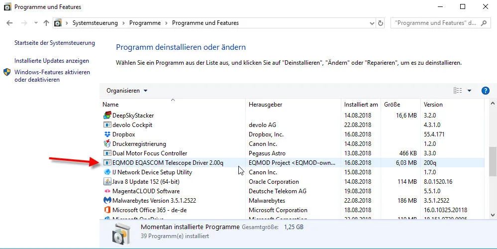
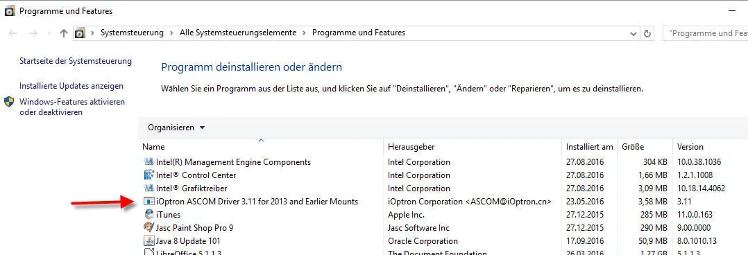
Nach der Installation findet man den EQMOD-ASCOM-Treiber für die Montierung HEQ5 Pro in der Systemsteuerung unter “Programme und Features”.

Abbildung 1: Windows Systemsteuerung –> Programm deinstallieren oder ändern (Google Drive: EQMOD-Driver.jpg)


EQMOD ASCOM Driver

Durch die Installation entsteht auf dem Desktop auch ein Shortcut  EQASCOM Toolbox.
Diese Toolbox ist eine einfache Möglichkeit EQMOD aufzurufen ohne eine richtige (große) Anwendung wie z.B. Guide oder Cartes du Ciel dazu bemühen zu müssen.

Wenn jetzt die SynScan-Handbox der HEQ5 Pro-Montierung per seriellem Kabel (siehe: Skywatcher HEQ5 Pro) mit dem Windows-Computer verbunden ist, kann man auf diesen Shortcut klicken, um die Verbindung herzustellen.

ASCOM-Treiber für die Montierung iOptron SmartEQ Pro

Für meine Montierung iOptron SmartEQ Pro finden wir auf der Website des Herstellers  den ASCOM-Treiber für die SmartEQ:

Der Treiber unterstützt nicht die Funktion “ASCOM Pulse Guiding”  was für PHD2 Guiding wichtig wäre.
Siehe dazu: http://www.iceinspace.com.au/forum/showthread.php?t=116706

Nach der Installation findet man den ASCOM-Treiber für die SmartEQPro in der Systemsteuerung unter “Programme und Features”.

Abbildung 2: Installierte ASCOM-Treiber (Google Drive: ASCOM_Treiber_iOptron_SmartEQPro.jpg)


ASCOM-Treiber für iOptron SmartEQ Pro

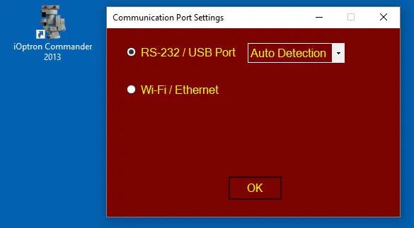
Durch die Installation entsteht auf dem Desktop auch ein Shortcut  iOptron Commander 2013.

Wenn jetzt die Go2Nova-Handbox der SmartEQ-Montierung per seriellem Kabel (siehe: iOptron SmartEQ Pro) mit dem Windows-Computer verbunden ist, kann man auf diesen Shortcut klicken, um die Verbindung herzustellen.

Abbildung 3:  iOptron Commander –> Communication Port Settings (Google Drive: iOptronCommander.jpg)


iOptron Commander: Port Stettings

In Planetarium software, select “iOptron ASCOM Driver for 2013 and Earlier Mount”

ASCOM-Treiber für die Kamera ZWO ASI294MC Pro

Für meine Kamera ASI294MC Pro finden wir auf der Website des Herstellers:

Nach der Installation findet man den ASCOM-Treiber für die Altair GPCAM in der Systemsteuerung unter “Programme und Features”.

ASCOM-Treiber für die Kamera Altair GPCAM

Für meine Kamera Altair GPCAM finden wir auf der Website des Herstellers:

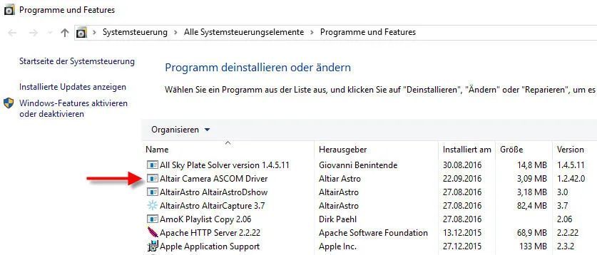
Nach der Installation findet man den ASCOM-Treiber für die Altair GPCAM in der Systemsteuerung unter “Programme und Features”

Abbildung 4: Windows Systemsteuerung –> Programm deinstallieren oder ändern (Google Drive: ASCOM_Treiber_Altair_GPCAM.jpg)


ASCOM-Treiber für Altair Camera

Wenn jetzt die Altair GPCAM per USB-Kabel mit dem Windows-Computer verbunden ist, kann man eine Kamera-Software, die ASCOM-Kameras unterstützt  (z.B. myCam, Altair Capture, ShapCap,…)  aufrufen, um das Bild zu testen und Aufnahmen zu machen.

ASCOM-Treiber für den Motor-Focusser “Pegasus Astro”

Als Motor-Fokusser habe ich einen Pegasus Astro erworben (neu aber: ZWO EAF), der ebenfalls per ASCOM angesprochen werden kann…

Für meinen Motor-Fokusser Pegasus Astro finden wir auf der Website des Herstellers:

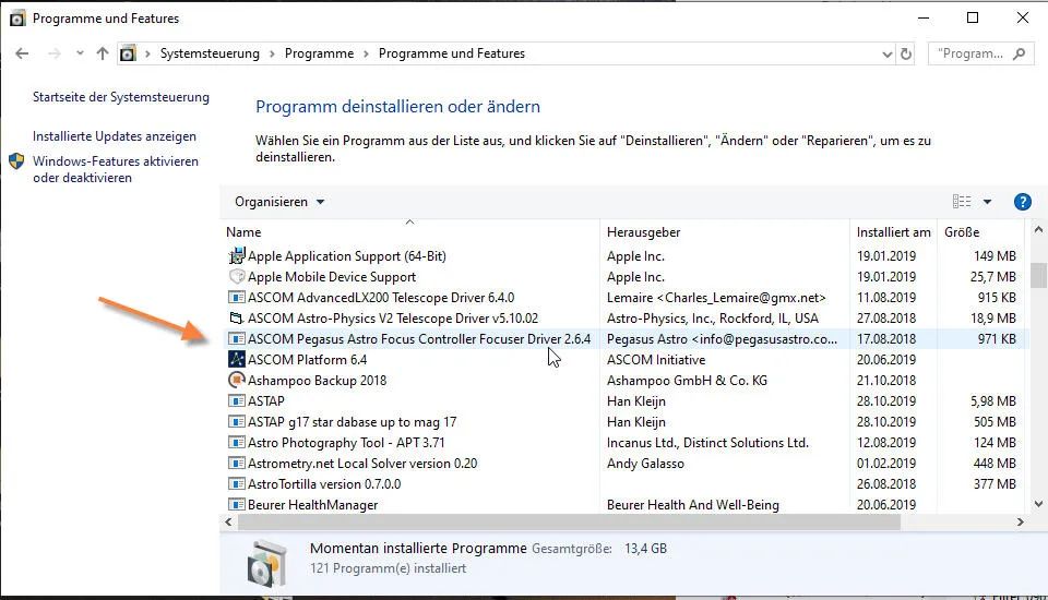
Nach der Installation findet man den ASCOM-Treiber für den Pegasus Astro Motor Focusser in der Systemsteuerung unter “Programme und Features”

Abbildung 5: Windows Systemsteuerung –> Programm deinstallieren oder ändern (Google Drive: PegasusAstroMotorFocusser-00.jpg)


Pegasus Astro Motor-Focus ASCOM-Treiber

Windows-Treiber (native drivers)

Die ASCOM-Treiber stehen in dem Ruf, nicht alle Funktionen der Geräte gut zu unterstützen. Delshalb arbeitet manche Astro-Software alternativ zu den ASCOM-Treibern auch gerne mit sogenannten “native” Treibern.

Windows-Treiber für die ZWO ASI294MC Pro

Von der Web-Seite des Herstellern ZWO kann man sich auch die sog. native Treiber (Windows Treiber) für die Kamera ASI294MC Pro herunterladen.

Download Link: https://astronomy-imaging-camera.com/software-drivers

Installiert: ZWO_ASI_Cameras_Driver 3.0.0.11   (21. Sept. 2020)

Windows-Treiber für die Altair GPCAM

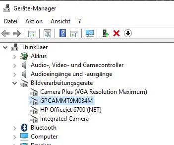
Zusätzlich zu den o.g. ASCOM-Treibern kann man für die Kamera Altair GPCAM auch den “Windows-Treiber” installieren. Zur Kontrolle kann man den Windows-Geräte-Manager aufrufen, wo Kameratreiber unter “Bildverarbeitungsgeräte angezeigt werden…

Abbildung 6: Windows Gerätemanager –> Bildbearbeitungsgeräte (Google Drive: Altair_GPCAM_Geraetemanager.jpg)


GPCAM Native Driver im Geräte-Manager

Astrofotografie: Plate Solving mit All Sky Plate Solver

Gehört zu: Astro-Software,  Plate Solving
Siehe auch: Software Platesolve2, Software APT, Platesolving mit ASTAP, ASI294MC Pro
Benutzt: Fotos aus Google Drive

Stand: 01.03.2022

Die Software “All Sky Plate Solver”

Zum Plate Solving verwende ich haupsächlich die kostenlose Software “All Sky Plate Solver” (kurz: ASPS),  die ohne eine andere Software, also “stand alone“, verwendet werden kann. Die Bildquellen können ganz einfach JPG-Bilder oder FITS-Bilder sein, die irgendwo auf dem Notebook liegen (also keine Kamera, kein ASCOM, kein garnichts, einfach “Stand Alone”). Als Ergebnis des Solven werden die Koordinaten des Bildmittelpunkts, der Drehwinkel gegen die Nordrichtung und einige weitere Daten ermittelt.

Später, nachdem man die Plate Solving Funktion “stand alone” getestet hat, ist es natürlich interessant, sie in seine Astro-Foto-Software zu integrieren (z.B. APT), und damit SYNC und GOTO zu machen. Dann ist der Ablauf: Foto machen, Platesolven, Montierung SYNCen.

Das Plate Solving erfolgt als “Blind Solving”; d.h. es muss kein “ungefährer” Ausgangspunkt angegeben werden. Im Gegensatz dazu gibt es auch ein sog. “Near Solving” wo ungefähre Ausgangskoordinaten angegeben werden müssen. Ein Beispiel für dieses Near Solving ist die auch kostenlose Software Platesolve2 von Planewave oder auch ASTAP.

Einrichtung der Software All Sky Plate Solver

Neben der eigentlichen Software “All Sky Plate Solver” werden zwei Dinge benötigt:

  1. Index-Files (der Sternkataloge) passed zu Brennweite, Pixelgröße und FoV (s.u.)
  2. Eine lokale Installation von astronomy.net unter Cygwin

Eine lokale Installation von Astronomy.net befindet sich auf meinem Computer unter: D:\bin\Astronomy.net Local Server (wohl weil ich irgendwann mal AnSvr installiert hatte)

Bevor man dann Solven kann, muss man konfigurieren:

  • Unter “Settings” -> “Plate Solver Settings” Brennweite (510mm) und Pixelgröße (4,63 µm) sehr genau  angeben.
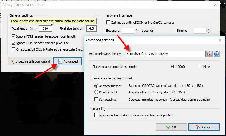
  • In den “Plate Solver Settings” gibt es eine Schaltfläche “Advanced”. Dort stellen wir ein:
    – Ordner, wo sich die lokale Astrometry.net Library befindet: C:\Users\<userid>\AppData\Local\Astrometry
    Epoche: J2000
  • Unter “Index” -> “Index Installation Wizzard” Index-Files aus dem Internet herunterladen. Dies muss man einmalig als vorbereitende Aktion für jedes “Field of  View” d.h. jede verwendete Kombination aus Brennweite, Pixelgröße und Sensorgröße (4144×2822) machen.

Dann kann’s losgehen: Meine Astrofotos werden meist nach 10 bis 30 Sekunden “gesolved” d.h. Rektaszension und Deklination des Bildmittelpunkts sowie der Drehwinkel gegen die Nordrichtung werden angzeigt. Was kann ich damit anfangen?

  1. Mit “Browse Solved Image” kann das Bild mit eingeblendetem Koordinatengitter betrachtet werden. Allerdings werden auf dem “Solved Image” zwar DSOs beschriftet aber leider nicht die Sterne. Anhand der nun bekannten Koordinaten können die Namen einzelner Sterne auf der Aufnahme auch ermittelt werden.
  2. Über eine ASCOM-Schnittstelle können die Bild-Koordinaten an eine angeschlossene Goto-Montierung zwecks “SYNC” übertragen werden. Das ist sinnvoll, wenn das Teleskop (die Optik) zu diesem Zeitpunkt unverändert in die gleiche Richtung zeigt, wie zum Zeitpunkt der Aufnahme.
  3. Bei bekannten Koordinaten des Bildes kann eine “Photometrische Farbkalibration” sicherer durchgeführt werden (dazu wird nächmich auch eine Art Plate Solving gemacht). Software, soetwas kann ist z.B. Regim und auch SiriL.

Weitere Funktionen des All Sky Plate Solver

  • Synchronisation einer Goto-Montierung über ASCOM (Koordinaten des Bildmittelpunkts an die Montierung schicken)
  • Direktes Aufnehmen eines Bildes einer über ASCOM angeschlossenen Kamera (z.B. Altair GPCAM) mit anschließendem Plate Solving    (funktioniert es?)
  • Sequence Analysis  (eine Aufnahmeserie liegt in einem Ordner: Bescheibung hier weiter unten!)
  • Integration in APT, Voyager, CCDCommander u.a.
  • Fast Polar Alignment (beta)

Fast Polar Alignment mit All Sky Plate Solver

Diese Funktion ist neu als sog. “Beta”. Erforderlich ist eine Verbindung zur Kamera (ASCOM oder…) sowie eine Verbindung zur Montierung (ASCOM).

Quelle

http://www.astrogb.com/astrogb/All_Sky_Plate_Solver.html

Probleme mit All Sky Plate Solver

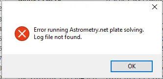
Ab und zu kann All Sky Plate Solver ein Foto nicht solven und bringt eine merkwürdige Fehlermeldung: Error running Astrometry.net plate solving. Log file not found.

Abbildung 1: All Sky Plate Solver – astrometry.net Error (Google Drive: AllSkyPlatesolver_Error01.jpg)


AllSkyPlatesolver: Error Astronomy.net not found

Das Log-File sollte stehen in: C:\Users\<user-name>\AppData\Local\Astrometry\temp

Es scheint, die Installation von Astrometry.net defekt zu sein….

Installation von All Sky Plate Solver

Download von:  http://www.astrogb.com/astrogb/All_Sky_Plate_Solver.html

Meine Version: 1.4.5.11 vom April 2016

Ausführen der Installation

Während der Installation auf meinem Windows-Computer bemängelt All Sky Pate Solver, dass noch Applikationen laufen, die geschlossen werden müssten, sonst kann er nicht:

  • Copernic Desktop Search Service
  • Intel(R) Dynamic Application Loader Host Interface Service
  • Intel(R) Management and Security Application Local Management Service

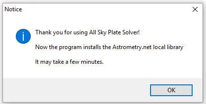
Bei einer vollständigen Neu-Installation sollte auch der “Astrometry.net Local Server” (so etwas wie AnSvr) vorher gelöscht worden sein. Die Installationsroutine von ASPS erkennt das und installiert Astrometry.net auch neu:

Abbildung 2: All Sky Plate Solver – astrometry.net local library (Google Drive: AllSkyPlatesolver_Astrometry.jpg)


All Sky Plate Solver

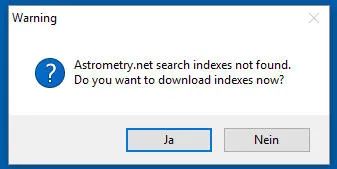
Bei einer vollständigen Neu-Installation erkennt die Installationsroutine nun, dass keine Index-Dateien da sind und fragt, ob es diese auch installieren darf:

Abbildung 3: All Sky Plate Solver – Index-Dateien (Google Drive: AllSkyPlatesolver_Astrometry2.jpg)


AllSkyPlateSolver: Index Files not found

Die Index-Dateien müssen entsprechend dem Gesichtsfeld (Field of View = FoV) ausgewählt werden und bei bestehender Internet-Verbindung heruntergeladen werden. Gespeichert werden diese Index-Dateien dann (bei Windows 10) im Ordner:

C:\users\userid\AppData\Local\Astrometry\usr\share\astrometry\data

Diesen Ordner kann man in den Advanced Settings auch verändern:

Abbildung 4: All Sky Plate Solver – Advanced Settings (Google Drive: AllSkyPlatesolver_Advanced.jpg)


AllSkyPlateSolver: Advanced Settings

Wobei %LocalAppData% bei meinem Windows 10 Notebook liegt auf: C.\Users\userid\AppData\Local

Arbeiten mit All Sky Plate Solver: Ein Beispiel Schritt für Schritt

Ich habe meine Sony NEX-5R (APS-C-Sensor, Pixelgröße 4,8µ) an mein LidlScope (f=700mm) geschraubt (fokal) und mit GoTo mitten in den Nordamerikanebel geschossen: Foto DK_20160711_08870.jpg.

Vom Nordamerikanebel war natürlich nix zu sehen, weil das Gesichtsfeld viel zu klein war (1,9° x 1,3°) und weil der Himmel mitten in Hamburg viel zu hell für dieses Objekt ist. Aber auf dem Foto sind Sterne zu sehen – aber welche?

Schritt 1: Focal Length & Pixel Size

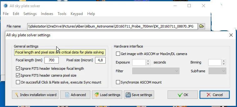
Zuerst stelle ich die Software “All Sky Plate Solver” auf mein Teleskop  f=700 und die Pixel Size meines Sensors 4,8µ ein.

f=700 galt für mein LidlScope, f=510 gilt für mein Orion ED80/600 mit Reducer.

Die Canon EOS 600D hat 4,3µ und 5184×3456 Pixel,
Die ZWO ASI294MC Pro hat 4,63µ und 4144×2822 Pixel,
Die Sony NEX-5R hat 4,8µ und 4912×3264 Pixel

Abbildung 5: All Sky Plate Solver Settings – Focal length & Pixel size (Google Drive: AllSkyPlatesolver_Settings.jpg)


All Sky Plate Solver General Settings

Schritt 2: Index Files

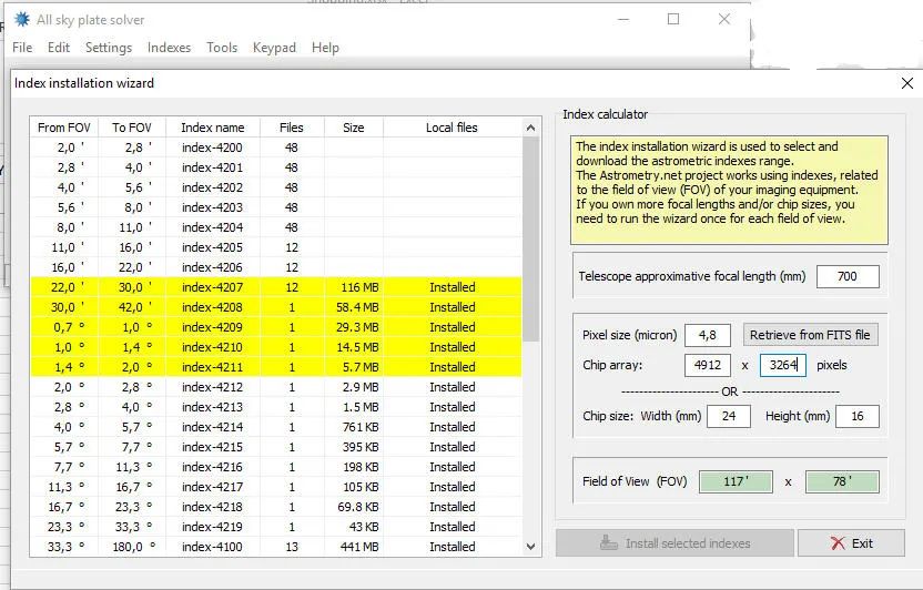
Dann prüfe ich, ob die Index-Dateien für diese Konfiguration (f=700mm, Pixel=4,8µ, Sensor=4912  x 3264) bereits geladen wurden. Dabei kommt es hier auf das Field of View (FoV) an. Wir brauchen dazu die Angaben f=700mm, Pixel=4,8µ, Sensor=4912  x 3264.

Abbildung 6: All Sky Plate Solver – Index installation wizard (Google Drive: AllSkyPlatesolver_IndexWizard.jpg)


All Sky Plate Solver: Index Wizard

Der Index Installation Wizard markiert die erforderlichen Index-Files gelb und wir sehen, dass in diese Fall die Index-Files bereits geladen sind. Falls das nicht der Fall sein sollte, werden die fehlenden Index-Files nach Klicken auf die Schaltfläche “Install selected indexes” herhuntergeladen.

Schritt 3: File Name of the Picture

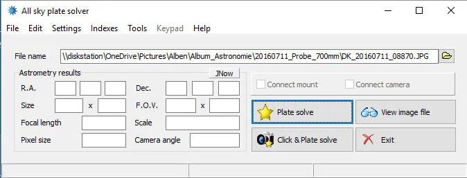
Nun kann ich den Dateinamen des zu “solvenden” Fotos eingeben: DK_20160711_08870.jpg

Abbildung 7: All Sky Plate Solver – Solven eines Testbildes (Google Drive: AllSkyPlateSolver_Filename.jpg)


All sky plate solver: File name

Schritt 4: Plate Solving Ergebnisse

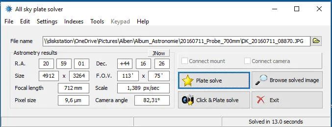
Wenn  ich nun auf die Schaltfläche “Plate solve” klicke, beginnt der All Sky Plate Solver den Solving-Prozess und zählt seine Sekunden hoch. Wir haben alles richtig gemacht und es erscheinen nach 13,0 Sekunden die Ergebnisse des Solving: R.A. und Dekl. der Bildmitte, Kamera Winkel etc.:

Abbildung 8: All Sky Plate Solver: Ergebnisse (Google Drive: AllSkyPlateSolver_Results.jpg)


All Sky Plate Solve: Results

Schritt 5: Browse solved image

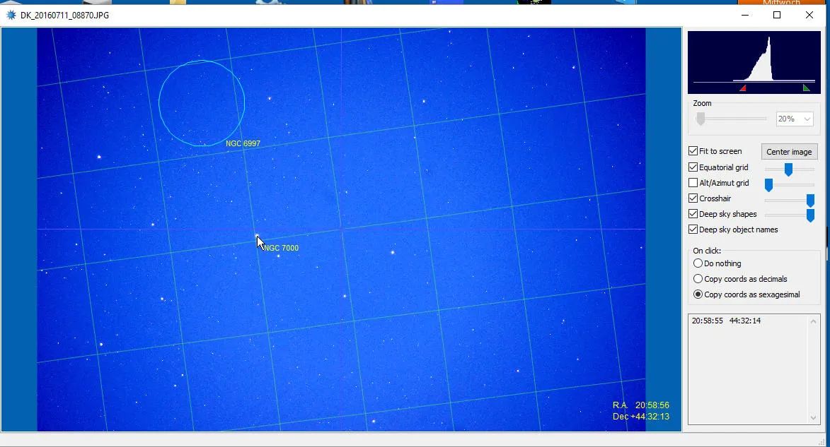
Nun kann ich das “gesolvte” Foto in einem Image-Browser betrachten: Schaltfläche “Browse solved image”. Mit JPG-Bildern hat das immer funktioniert, bei FITS-Bildern hat das aber leider nicht immer funktioniert – es könnte evtl. daran liegen, dass es unterschiedliche Varianten des FITS-Formats gibt.

Abbildung 9: AllSkyPlateSolve Ergebnis: Browse solved image (Google Drive: AllSkyPlateSolver_Browse.jpg)


All Sky Plate Solve: Browse solved image

Rechts nehme ich normalerweise immer folgende Einstellungen vor:

  • Um zunächst das ganze Bild zu sehen, klicke ich oben rechts auf “Fit to screen”
  • Das “Alt/AZ Grid” schalte ich immer aus.
  • Und dann markiere ich “On Click, Copy Coordinates”

Die Koordinaten des Bildmittelpunkts habe ich zwar (Crosshairs), aber leider sind die Sterne nicht mit ihrem Namen beschriftet (DSOs kann der All Sky Plate Solver eintragen, aber keine Sternnamen).

Wenn ich mit der Maus über das Bild fahre, werden R.A. und Dekl. immer angezeigt und wenn ich mit der Maus klicke werden R.A. und Dekl. sogar rechts unten hinkopiert. So kann ich R.A. und Dekl. eines markanten Sterns ermitteln und festhalten. Hier nehme ich den hellen Stern etwas links von der Mitte, wofür angezeigt werden:
20h 58m 55s und 44° 32′ 12″

Nun muss ich “nur” noch herausbekommen, wie dieser Stern nun eigentlich heisst.  Beispielsweise sagt mir Guide (Menüleiste -> Finden -> Koordinaten -> …), dass es der Stern SAO 50298 ist.

All Sky Plate Solver:  Alle Bilder in einem Ordner  = “Sequence Analysis”

Wenn ich eine ganze Reihe von Aufnahmen in einer Nacht gemacht habe, wäre es mühsam, damit einzeln die o.g. Schritte zum Solven durchzuführen. All Sky Plate Solver hat da eine einfachere Möglichkeit:

  • Menüleiste -> Tools -> Sequence Analysis

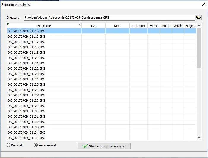
Im Feld “Directory” gebe ich nun den Ordnernamen an, in dem sich alle zu solvenden Aufnahmen befinden, dann lädt All Sky Plate Solver die Dateinamen dieses Ordners in seine Tabelle (erste Spalte).

Abbildung 10: All Sky Plate Solver: Sequence Analysis (Google Drive: AllSkyPlateSolver_Sequence-05.jpg)


All Sky Plate Solver: Sequence Analysis

Danach klicke ich auf die Schaltfläche “Start astrometric analysis” – und los geht’s.

In der Statusleiste ganz unten erscheint “Work in progress…” und die Sekunden-Zählung rauscht ab. Das wird jetzt allerdings eine ganze Weile dauern kann. Ggf. ist es morgens zum Früstück fertig (so sagte ein Astro-Kollege zu mir).

Wichtig ist, das man vorher in den Settings Focal length und Pixel size richtig eingestellt hat, sonst sieht man hier gleich Blödsinn.

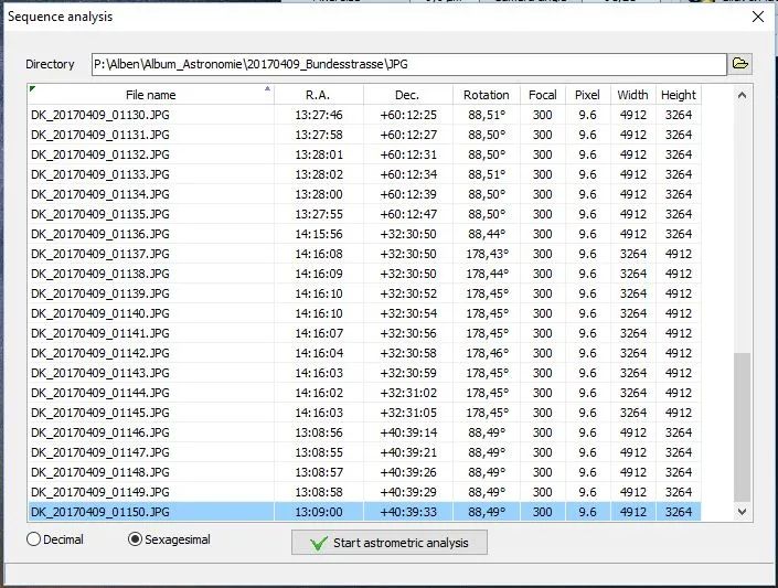
Wenn endlich die Astrometrie fertig ist, haben wir folgende Ergebnisse:

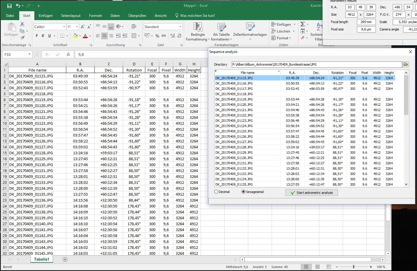
Abbildung 11: All Sky Plate Solver: Sequence Analysis (Google Drive: AllSkyPlateSolver_Sequence-06.jpg)


AllSkyPlateSolver Sequence Analysis: Ergebnisse

Diese tabellarischen Ergebnisse können wir nun mit einem kleinen Kniff direkt in Excel importieren: Wir klicken auf das kleine Dreieck links oben in der Spaltenüberschrift “File name”.

Das Ergebnis in Excel sieht dann so aus:

Abbildung 12: Sequence Analysis in Excel (Google Drive: AllSkyPlateSolver_Sequence-07.jpg)


AllSkyPlateSolver: Sequence Analysis:  Export to Excel

Kleines Problem: Pixelsize mit Dezimalpunkt (statt Komma)

Excel kann die Pixelsize in ein Datum uminterpretieren – wegen des Punktes statt des Kommas.

  • Lösung 1:    =ZAHLENWERT(WECHSELN(TEXT(F17;”T.M”);”.”;”,”))       (wenn Spalte 17 die Pixelsize enthält)
  • Lösung 2:   Zellen formatieren… -> Benutzerdefiniert -> Typ ändern von TT.MMM in TT.MM
  • Lösung 3:  Gebietsschema ändern  (Deutschland -> Vereinigte Staaten)

All Sky Plate Solver: SYNC mit Goto-Montierung

Wenn die Richtung des Teleskops (der Optik) zwischen dem Zeitpunkt der Aufnahme und dem Zeitpunkt des Plate Solving nicht verändert wurde, wäre es sinnvoll, die Montierung auf diesen Punkt zu synchronisieren.

Das Notebook, auf dem die Software “All Sky Plate Solver” läuft ist mit einem speziellen seriellen Kabel mit der Go2Nova-Handbox verbunden.

Auf dem Notebook ist ebenfalls der ASCOM-Treiber für die Montierung iOptron SmartEQ Pro (neu: Skywater HEQ5 Pro) installiert und in der Software “All Sky Plate Solver” konfiguriert….

Astrofotografie: Plate Solving mit Nova Astrometry

Gehört zu: Plate Solving
Siehe auch: AnSvr, FITS Header
Benutzt: Fotos aus Google Drive

Stand: 26.07.2024

Plate Solving mit Nova Astrometry

Eine ganz einfache Möglichkeit zum Plate Solving bietet Nova Astronomy als Online-Service im Internet. Es lässt sich auch lokal auf einem Windows-Computer installieren.

  • Local Astrometry.NET Install (AnSvr)    http://adgsoftware.com/ansvr/
  • AnSvr wurde ursprünglich für Sequence Generator Pro (SGP) entwickelt
  • AnSvr wird intern von All Sky Plate Solver verwendet
  • AnSvr kann aber auch z.B. mit AstroImageJ, ACP oder PinPoint verwendet werden

Preliminary: Was ist “WCS”?

Im Zusammenhang mit astronomischen Fotos taucht immer wieder das Kürzel “WCS” auf: Anscheinend gibt es Fotos mit WCS und Fotos ohne WCS.

WCS steht für “World Coordinate System”.

Die WCS-Daten eines Fotos bestehen aus Keywörtern und Werten; z.B. Author, Epoche, Maßstab, Koordinaten (Rektaszension, Deklination) eines jeden Pixels. Siehe dazu auch: FITS Header.

Nova Astronomy als lokale Installation

Download von: http://adgsoftware.com/ansvr

Wird installiert in: D:\bin\Astrometry.net Local Server

Läuft unter Cygwin, was in den Ordner cygwin_ansvr installiert wird.

Benötigt wird eine Library mit Index-Dateien und ein Service, der gestartet werden muss.

AnSvr Service

Das Starten des Service geschieht bei Windows durch einen Eintrag im Ordner “Autostart“:  start_ansvr.bat

Durch diese bat-Datei wird der Dienst in D:\Users\<user>\AppData\Local\cygwin_ansvr gestartet.

Allerdings heisst der Autostart-Ordner unter Windows 10 jetzt Startup und kann durch “shell:Startup” aufgerufen werden. Bei mir befindet sich dieser Ordner hier:

D:\Users\<user>AppData\Roaming\Microsoft\Windows\Start Menu\Programs\Startup

Test-Aufruf des AnSvr-Service

Um testweise festzustellen, ob der AnSvr-Service auch tatsächlich läuft, kann man im Web-Browser die URL http://127.0.0.1:8080/api/config aufrufen.

AnSvr Library

Der ansvs-Service muss immer seine Index-Dateien finden.  Diese werden auch Library genannt. Bei mir befinden sich diese Index-Dateien an zwei Stellen:

  • C:\cygwin\usr\share\astrometry\data
  • C:\Users\<user>\AppData\Local\Astrometry\usr\share\astromery\data

Lokale Benutzung des AnSvr-Service

Auf Cloudy Nights hat der user Jusasi etwas fabriziert: https://www.cloudynights.com/topic/613555-astrometry-api-lite-local-astrometrynet-api-with-installer/

Nova Astrometry als Online-Service

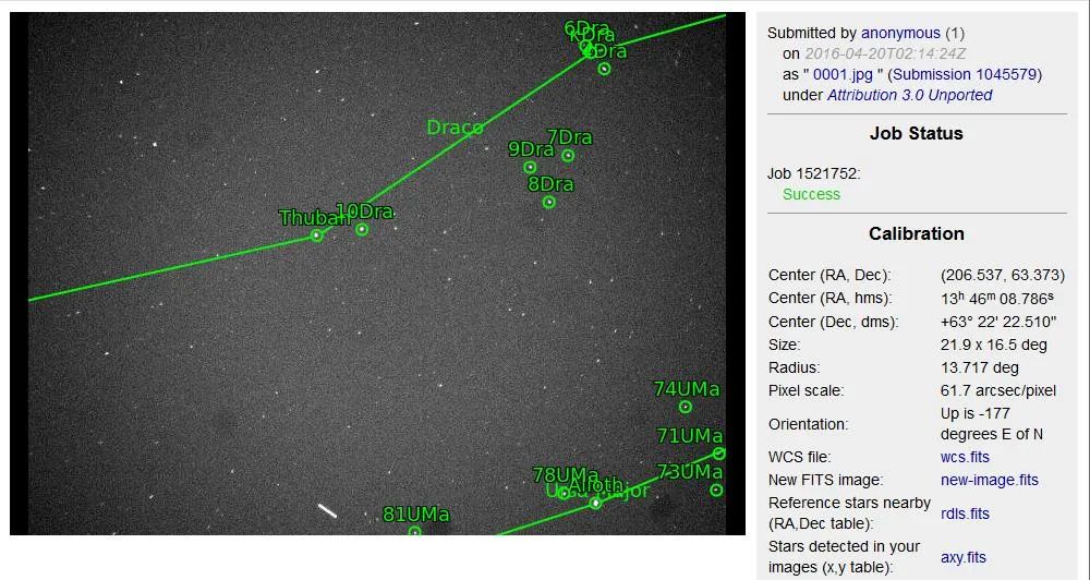
Wenn ich das gleiche Bild an nova.astronomy.net schicke, bekomme ich zusätzlich zu den Daten:

RA 13h 46m 08s, Dec 63° 22′ 22″, FoV 21,9° x 16,5°

Abbildung 1: Nova Astrometry  Bild mit den eingezeichneten gefunden Sternen (Google Drive: Nova_Astrometry_01.jpg)


Plate Solving mit Nova Astrometry 01

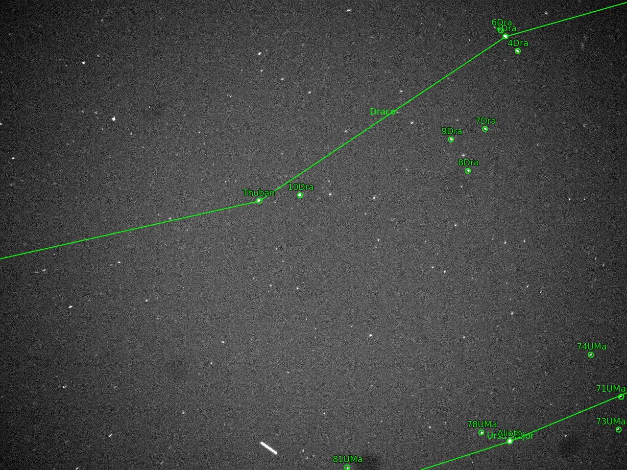
Abbildung 2: Nova Astrometry- Gesolvedes Bild als “Full Size” (Google Drive: Nova_Astrometry_02.jpg)


Platesolving mit Nova Astrometry: Full Size

Astrofotografie Software: AstroTortilla for Plate Solving

Gehört zu: Astrofotografie Software
Siehe auch: Plate Solving, AnSvr, Polar Alignment, APT, N.I.N.A.
Benutzt: Fotos aus Google Drive

Stand: 02. Juni 2023

Astrofotografie mit der Software AstroTortilla

Zusammenfassung

Anwendungsbereich von AstroTortilla

Mit AstroTortilla kann man eine Kamera ansteuern und dann Plate Solving machen. Die Plate-Solving-Ergebnisse können als SYNC-Points (Alignment Points) zur Teleskopsteuerung verwendet werden. Dadurch funktioniert ein Goto ohne 3-Star-Alignment.

Gliederung

Meine ersten Schritte mit der Software AstroTortilla

Installation von AstroTortilla

Download: https://sourceforge.net/projects/astrotortilla/files/AstroTortilla-0.7/AstroTortilla-0.7.0.0-x64.exe/download

Wenn man AstroTortilla auf Windows installiert, wird ganz automatisch das Cygwin mit installiert. Anscheinend benötigt das AstroTortilla um das API zu astronometry.net zu realisieren.

Setup einer Kamera in AstroTortilla

AstroTortilla möchte als erstes eine Kamera und als zweites ein Teleskop “haben”.

Als Kamera hat man folgendes zur Auswahl:

Kamera-Setup als “ASCOM Camara”

Da ich gerade meine erste schicke AstroCam erstanden hatte (eine Altair GPCAMMT9M034M) und da auch etwas von ASCOM drauf stand, habe ich “ASCOM Camera” als erstes ausprobiert.

Als Basis benötigt man zu allerest die ASCOM-Platform. Auf der Web-Seite http://ascom-standards.org finde ich zum Download: ASCOMPlatform62.exe

Als zweites brauche ich den ASCOM-Kamera-Treiber. Den gab es auf der Herstellerseite: http://cameras.altairastro.com/

Wenn ich meinen Windows-Computer nun neu starte und dann zur Kontrolle SharpCap aufrufe, kann ich tatsächlich eine “Altair Astro Camera ASCOM Driver” im Dropdown sehen und wenn ich diese auswähle erscheint auch tatsächlich ein Bild – SUPER!

Auch in AstroTortilla kann ich jetzt unter “Camera” eine “ASCOM Camera” auswählen und komme dann nach dem Klicken auf den Setup-Botton auf den “ASCOM Camera Chooser” wo ich die “Atair Astro Camera ASCOM Driver” aussuchen kann.

Nachdem nun alles richtig eingestellt ist, könnte ich auf den Button “Capture and Solve” drücken, aber die Cam ist ja noch garnicht auf den Sternenhimmel gerichtet. Ich könnte aber bereits vorhandene Astro-Fotos zum Solven ausprobieren, in dem ich als Camera nicht die wirkliche Kamera angebe, sondern aus dem Kamera-Dropdown “File Open dialog” auswähle.

Kamera-Setup als “File Open dialog”

Aus dem Kamera-Dropdown haben wir nun “File Open dialog” ausgewählt. Der Setup-Button hat dann keine Funktion, aber wenn man jetzt auf den Button “Capture and Solve” drückt, kann man ein bereits vorhandenes Astrofoto auswählen, was dann “gesolved” wird…

Testfall #1

  • Ich habe ein Foto ausgewählt: ShapCap Captures > 2016-04-17 > Capture > 22_45_53 > 0001.fits
  • Nach 32 Sekunden liefert AstroTortilla mit dem Solver “Local astrometry.net” ein Ergebnis:
  • RA: 13h 46m 39,05s Dec: 63° 18′ 18,67″ Exposure 5.0 s Field size: 21,42° x 16,28° Rotation: 183,76 Flipped

Abbildung 1: Platesolving mit Astro Tortilla (Google Drive: AstroTortilla01.jpg)

Vergleiche: Abbildung 10


AstroTortilla01

Ein wunderschönes Ergebnis. Mit den Koordinaten ist wohl die Bildmitte gemeint. Aber welche Sterne sind den nun tatsächlich auf dem Foto?

Tutorial (Imaging): Setting up and Using AstroTortilla for Plate Solving

Copyright: Light Vortex Astronomy

Quelle: http://www.lightvortexastronomy.com/tutorial-setting-up-and-using-astrotortilla-for-plate-solving.html#Section1

AstroTortilla is one of those programs that may seem overly complicated to set up and start using, hence this short tutorial for those interested. It is however a program that once you start using, you will not regret having spent the time to install it and set it up. Best of all, AstroTortilla is completely free and works wonders for plate solving. For those unaware, plate solving is a process by which software checks your astrophotograph for star patterns and determines what it is you are actually looking at. Why is this in any way important, though? Simple – when you tell your telescope to go to a deep space object, it will go to it but will probably miss and not have your chosen object centred in view. Of course, a decent three-star goto alignment prior to slewing to your target removes quite a lot of the error but:

  1. The goto alignment will very seldom provide you with perfect goto accuracy.
  2. Why bother picking multiple stars and aligning them perfectly when you would rather spend the time actually imaging your target?

It is here that AstroTortilla excels. You set up your telescope and CCD camera, you send your telescope to your target and then tell AstroTortilla to plate solve. It will capture an image with your CCD camera, analyse it to check where you are actually aiming and then slew your telescope to remove the goto error and centre your target. It can even iterate through this process until your target is very precisely centred within a chosen margin of error (default is 1 arcminute). I tend to only need a single iteration to get my target perfectly centred. If you are interested, you will need to sort out a couple of things beforehand:

  1. Your mount must be controlled via a laptop and the likes of EQMod or other such ASCOM software, through an EQDirect USB interface. This is paramount as AstroTortilla needs to interface with your mount directly via ASCOM.
  2. Download the latest version of AstroTortilla for free from this link.

​Please feel free to ask questions or leave comments via the comments section on the bottom of this page. Alternatively, you may send me a quick message through the About page, e-mail me via the button on the top-right of this website or contact me through forums or Facebook.

Tabelle 1: Inhaltsverzeichnis des Tutorials

1. Installing AstroTortilla

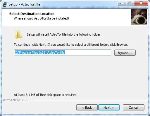
Though it may sound silly going through the installation process, there is a bit we need to pay close attention to. Choose to install AstroTortilla to the default directory.

Abbildung 2: AstroTortilla Installation Destination (Google Drive: AstroTortilla_setting_up_astrotortilla_-_1.1.jpg)


AstroTortilla Installation: Destination

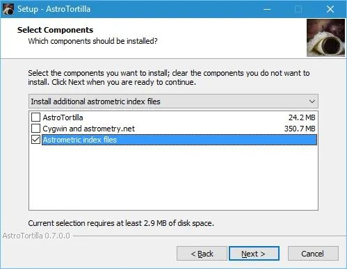
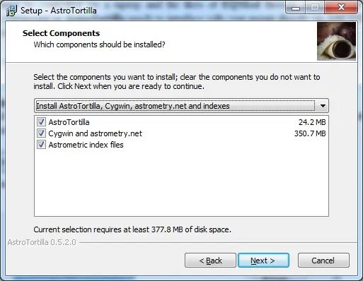
As we are installing everything from scratch, leave the default option “Install AstroTortilla, Cygwin, astrometry.net and indexes” selected with everything checked.

Abbildung 3: AstroTortilla Select Components (Google Drive: AstroTortilla_setting_up_astrotortilla_-_1.2.jpg)


AstroTortilla Components

If it were all installed but we simply wanted additional astrometric index files (these are the reference files that contain the star patterns to match up against your captured images and astrometric index files are different for different fields of view), we would select “Install additional astrometric index files”.

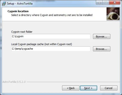
It is important to install Cygwin (part of AstroTortilla’s package) to its default directory.

Abbildung 4: AstroTortilla: Cygwin location (Google Drive: AstroTortilla_3927552_orig.jpg)


AstroTortilla Cygwin Location

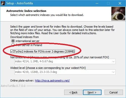
Abbildung 5: AstroTortilla Index selection (Google Drive: AstroTortilla_6754082_orig.jpg)

Vergleiche: Abbildung 9
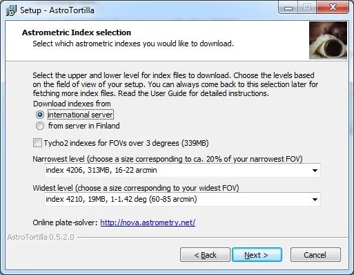

AstroTortilla: Index SelectionWe now reach the important stage that we need to carefully consider.

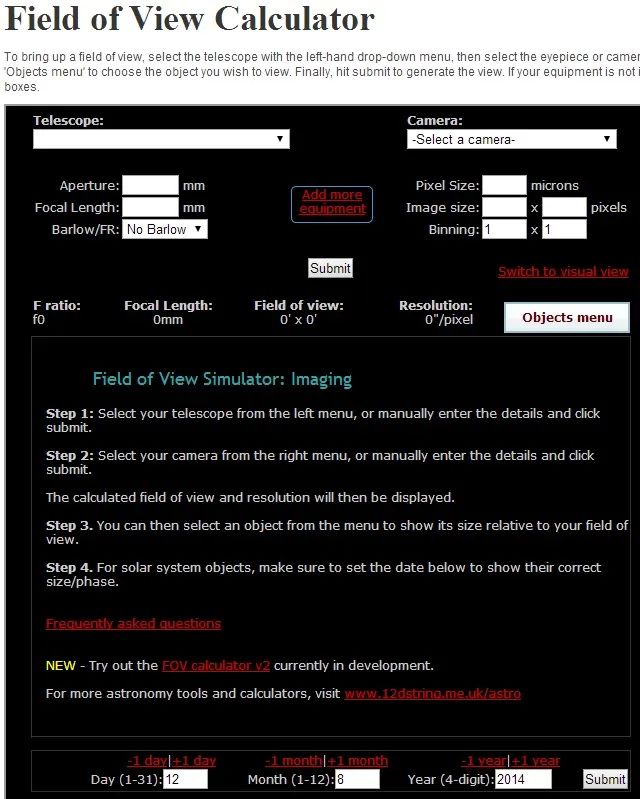
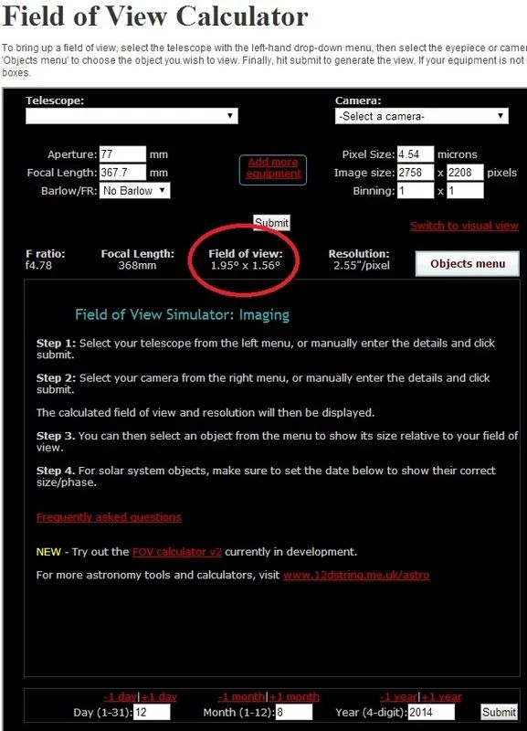
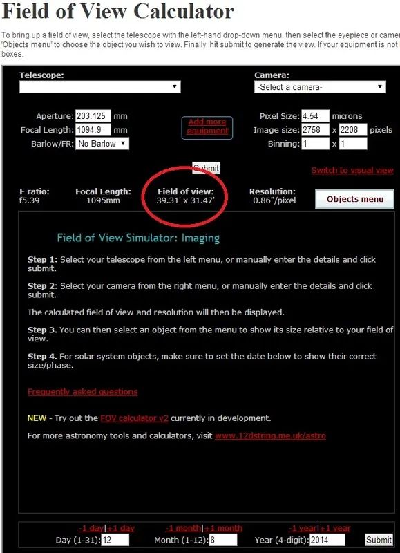
You may have multiple telescopes and multiple CCD cameras. Matching these up will naturally produce different fields of view and if we want to install AstroTortilla armed with all required astrometric index files to work on all your combinations, we will need to figure out the fields of view produced by your narrowest-field setup and your widest-field setup. For example, say you have two telescopes and one CCD camera. One produces a wide-field and another a narrow-field. It is easy to figure out the range of astrometric index files required. In order to calculate the fields of view, we can use the free, online Sky at Night Field of View Calculator.

Abbildung 6: Field of View Calculator (Google Drive: AstroTortilla_2763989_orig.jpg)


AstroTortilla: Field of View CalculatorYou may find your telescope and CCD camera listed and therefore you can simply select these (do verify the details are correct!). My CCD camera, the QSI 660wsg-8, was not on the list and neither were my telescopes. So, I therefore verified the details of my CCD camera with the manufacturer, QSI, and then manually entered my first telescope’s details (having measured the exact focal length beforehand – see another tutorial).

Abbildung 7: Field of View (Google Drive: AstroTortilla_4668114_orig.jpg)


AstroTortilla: Field of ViewI note that my Borg 77EDII with my QSI 660wsg-8 yields a field of view of 1.95 degrees x 1.56 degrees.

Now I enter my second telescope’s details.

Abbildung 8: Field of View (Google Drive: AstroTortilla_2351746_orig.jpg)


AstroTortilla: Field of View 2Finally, I note that my Altair Astro 8″ RC with my QSI 660wsg-8 yields a field of view of 39.31 arcminutes x 31.47 arcminutes.

Now we return to the AstroTortilla installation process. First I select my widest field of view. We always use the biggest number of the two. My widest field of view is 1.95 degrees x 1.56 degrees, so I take the field of view number to be 1.95 degrees (the largest number). From the astrometric index files list on Widest level, I select:

index 4212, 4.0MB, 2-2.83 deg (120-170 arcmin)

The range of 2 – 2.83 degrees clearly covers my 1.95 degrees. Now for the narrowest field of view. The installation suggests we select about 20% of our narrowest field of view, so let us do that. My narrowest field of view is 39.31 arcminutes x 31.47 arcminutes, so I take the field of view number to be 31.47 arcminutes (the smallest number). 20% of it is 6.294 arcminutes. From the astrometric index files list on Narrowest level, I select:
index 4203, 2.5GB, 5.6-8 arcmin
This range clearly covers 20% of my narrowest field of view, 6.294 arcminutes. ​

Abbildung 9: AstroTortilla Index selection (Google Drive: AstroTortilla_9919543_orig.jpg)

Vergleiche Abbildung 5: AstroTortilla_6754082_orig.jpg
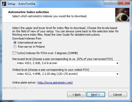

AstroTortilla: Index Selection 2

Please note the installation will actually download these two astrometric index files and every other one in-between them. Checking the file sizes, the astrometric index files for narrower fields of view are quite large and the entire download probably sums up to about 4.9GB in total for my telescopes and CCD camera. Your astrometric index files will probably differ from mine.

If indeed you only have one telescope and one CCD camera, then it is simpler. For example, let us say that I only have the Borg 77EDII telescope and QSI 660wsg-8 CCD camera. We calculated the field of view to be 1.95 degrees x 1.56 degrees for this setup. We therefore take our widest field of view here to be 1.95 degrees and the narrowest to be 1.56 degrees. 20% of the narrowest is then 0.312 degrees (or 18.72 arcminutes, multiplying by 60) and we have our numbers for selecting appropriate astrometric index files.

Once you have adequately selected your needed astrometric index files, proceed with the installation and finish it. No doubt the downloading of astrometric index files will take a while, depending on your Internet connection with the server.

2. Setting up AstroTortilla with Optimum Settings for Fast Plate Solving

When you first run AstroTortilla, it might look intimidating and perhaps even unrefined. It is however very powerful and you need not do much to configure it and get it running.

Abbildung 10: AstroTortilla (Google Drive: AstroTortilla01.jpg)

Vergleiche: Abbildung 1
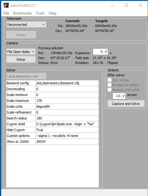
Let us first summarise the sections of this window.

Under Telescope, we connect to the telescope mount and once connected, you are shown your current telescope position in the night sky as well as your intended target. Basically when you issue a goto command for the telescope to slew to your target, it will most assuredly miss and you will notice the difference under Current and Target.

Under Camera, we connect to the CCD camera via compatible software such as Nebulosity, MaxIm DL, Backyard EOS, etc. We can also ask AstroTortilla to control the CCD camera directly via ASCOM or in fact, select File Open dialog and select an image that we have taken by our own means (without asking AstroTortilla to do it itself automatically). Here we also set the desired exposure time. Unless you are currently using a narrowband filter, 10 seconds usually suffices. If you are using a narrowband filter, it may be a good idea to switch to a regular LRGB filter. If you are using a refracting telescope and are already focused with say, Hydrogen-Alpha (or Sulphur-II), using Red would be a close match for focus (Green is a good match for Oxygen-III).

AstroTortilla will work even if you are slightly out of focus anyway. Using a regular LRGB filter, which is broadband, will allow a lot more light through and will produce more stars for plate solving in a shorter exposure time (this is particularly true for Luminance). Once plate solved, you can always switch back to your narrowband filter for imaging without ever touching the focus.

Under Solver, we can customise a couple of settings, and this is what we will do first and foremost. These settings tell AstroTortilla what field of view we are actually dealing with (to give it a head-start in plate solving and allowing it to take much less time), how many degrees off from your target you wish to look at, the noise tolerance, etc.

Under Actions, we set off AstroTortilla to do its job. It is of utmost importance that we always check Sync scope and Re-slew to target as these will make sure AstroTortilla does the job of centering your target in view and adding a sync point to EQMod (like a star alignment point) to correct future slewing accordingly. You could also of course check the third option Repeat until within and enter an amount of arcminute tolerance. Please note this will cause AstroTortilla to iterate through the process at least twice (first time to perform the initial error correction and second time to check resulting accuracy), with more iterations possible depending on how far off you are from your target after the first correction. The Capture and Solve button of course, sets it all off to do its magic.

The first thing we will do is change some settings in AstroTortilla, under the Solver section. Since I have two telescopes and one CCD camera, I have two setups I can possibly use. I will therefore create two settings files, one for each setup, so that in the future I can load up the one I need and set it off quickly.

The first settings we will change are Scale minimum and Scale maximum. These are where you tell AstroTortilla the minimum and maximum field of view possible. Let us say I am using my Altair Astro 8″ RC telescope first. This provided a field of view of 39.31 arcminutes x 31.47 arcminutes with my CCD camera. We will work with degrees rather than arcminutes and therefore dividing these numbers by 60 gives us the field of view to be 0.655 degrees x 0.525 degrees. We note then that the maximum is 0.655 degrees and the minimum is 0.525 degrees. We need not be 100% accurate (these numbers are a little rounded off) and so I will enter 0.5 in Scale minimum and 0.7 in Scale maximum. You may enter rounded off numbers as long as Scale minimum is below your actual minimum and Scale maximum is above your actual maximum.

Abbildung 11: AstroTortilla: Scale min&max (Google Drive: AstroTortilla_5681440_orig.jpg)


AstroTortilla: ScaleI will leave degwidth in Scale units as we are entering everything in degrees. Now we must edit Search radius. The default value of 180 is way too high. This means AstroTortilla will search 180 degrees around your target. This is quite simply savage as though we will miss the target, we will not miss it by 180 degrees! To be safe though, we will set 15 degrees, so I enter 15 here. Please keep in mind this value if it turns out AstroTortilla is not successfully plate solving your images. You may want to first try increasing it to 30 or even 45 just in case. You should never need to go higher than 45. Similarly, you may never be as far off as 15 degrees and so you may decrease it and test it out. As long as it plate solves, the lower this value is, the faster it will work.

Abbildung 12: AstroTortilla Search Radius (Google Drive: AstroTortilla_4239689_orig.jpg)


AstroTortilla: Search Radius

Finally, we will alter Custom options. The first option that is there by default is particularly important, –sigma 1. This defines the noise tolerance in analysing your captured image for plate solving. The default value of 1 is very, very small and pretty much any speck on your image may be considered a star. Even with a cooled CCD camera, this is certainly not the case and in fact, we do not want too many stars to be considered for plate solving as it would take ages. For a 10 second exposure (without a narrowband filter in place!), a much better value is something like 50 to 70. In fact, any value between 50 and 100 is good depending on the number and brightness of the stars in your field of view. This value is balanced out with exposure time, as you would imagine. I would set it to 70 and then just alter exposure time to suit. We leave the parameters –no-plots and -N none there but add two more. We will reiterate to AstroTortilla the field of view we expect. For this, we use the options -H and -L, which are widest field of view and narrowest field of view, respectively. I will stick to the same values as with Scale minimum and Scale maximum and therefore enter -H 0.7 -L 0.5 to the end of Custom options, after adding a space.

There are two more Custom options that are particularly interesting. These help speed up plate solving and are in some way related to one another. They are -r and –objs. The former, -r, need only be added as that. This command instructs AstroTortilla to sort the stars in order of brightest first, therefore allowing AstroTortilla to optimise the plate solving process as it starts with the brightest stars in your image. The second option to help speed up plate solving is rather to ensure that if it is going to fail, that it fails quicker rather than keeping you waiting. The parameter –objs command must be accompanied by a number, e.g. –objs 100. What this command does is instruct AstroTortilla to use a maximum of 100 stars for the plate solving (the developers generally recommend between 100 and 200 stars). After having sorted them in brightest-first, it seems like a good idea to restrict how many AstroTortilla should use as if it fails after the first and brightest 100, for example, there is a very, very good chance it will simply fail altogether. At that point of course you would adjust other parameters such as your exposure time. Please be aware however that these options are not always best. Sometimes you may want to include more stars than 100 or you may not want to restrict the number of stars used. This could be due to persistent plate solving failures. Feel free to remove the –objs command if you feel it necessary, though the -r command tends to be a good idea to leave active.

Abbildung 13: AstroTortilla Custom Options (Google Drive: AstroTortilla_5863500_orig.jpg)


AstroTortilla: Custom Options

Due to the length, you cannot see the entire Custom options line in the above screenshot. For reference, it reads:

–sigma 70 –no-plots -N none -H 0.7 -L 0.5 -r –objs 100
Nebulosity 3 for my imaging, with my QSI 660wsg-8 CCD camera. Also, I will be binning my images in 2×2 when it comes to plate solving as this will brighten the image significantly in the exposure time set and it will bring out more stars as well. Binning has the additional benefit that the file size and resolution is reduced by a factor of four, meaning that AstroTortilla will be much faster at processing the image and plate solving it. To set the software, camera and binning mode I will use, I simply select Nebulosity 2/3 from under Camera and then click Setup. Here, I select QSI 500/600 from the list, verify the directory for Nebulosity 3 is correct and select 2 in Binning.

Users of a DSLR, which cannot bin images, would benefit from setting Downscaling to 1 under Solver. This will at least downscale the image in order to make it faster to process and plate solve. Binning is most definitely preferable to downscaling simple because binning downscales by its very nature but at the same time, produces an image with a lot more brightness and more stars picked up. Downscaling alone simply makes the image smaller, with no added benefit to the stars detected.

Abbildung 14: AstroTortilla Camera Setup (Google Drive: AstroTortilla_8864129_orig.jpg)


AstroTortilla: Camera Setup Nebulosity

AstroTortilla is now customised for my Altair Astro 8″ RC and QSI 660wsg-8 so I save the settings to a new file, naming it appropriately for future reference.

Abbildung 15: AstroTortilla: Save Settings (Google Drive: AstroTortilla_4482496_orig.jpg)

Vergleiche Abbildung 19 AstroTortilla_6379424_orig.jpg
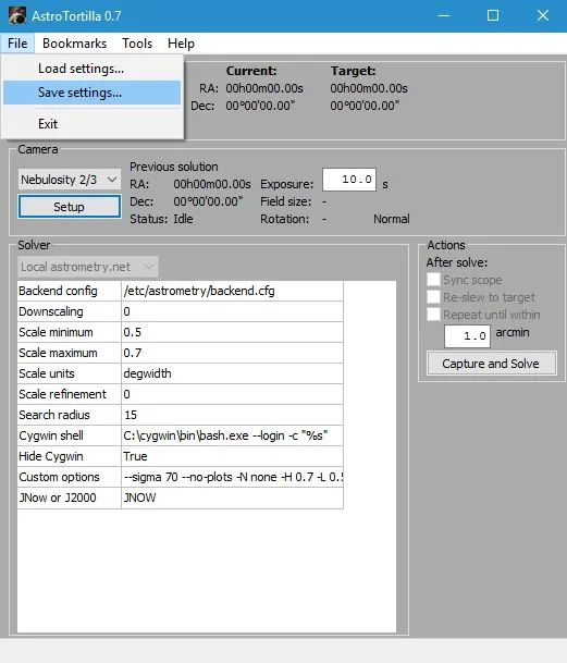

AstroTortilla: Save Settings

Abbildung 16: AstroTortilla: Save Settings (Google Drive: AstroTortilla_8117221_orig.jpg)

Vergleiche Abbildung 20 AstroTortilla_3770875_orig.jpg
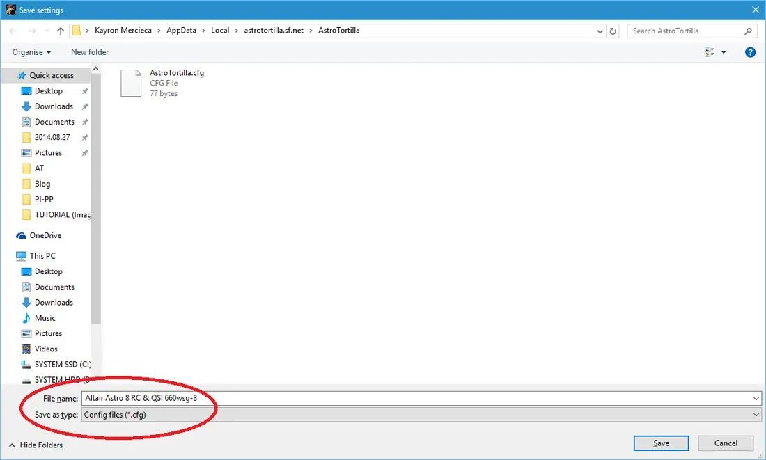

AstroTortilla Save Settings FileNow to customise AstroTortilla to my Borg 77EDII telescope with the QSI 660wsg-8 CCD camera. We note the field of view was calculated to be 1.95 degrees x 1.56 degrees. This will again define our values of Scale minimum and Scale maximum. We therefore enter 1.5 for Scale minimum and 2.0 for Scale maximum. Again, we are rounding off slightly below the actual minimum and above the actual maximum.

Abbildung 17: AstroTortilla  Scale (Google Drive: AstroTortilla_915917_orig.jpg)

Siehe Abbildung 11: AstroTortilla_5681440_orig.jpg
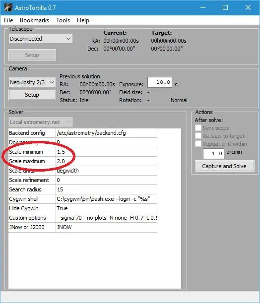

AstroTortilla: Scale 2We will leave Search radius at 15, like before, and –sigma 70 in Custom options (for noise tolerance). I of course will alter the -H and -L options to enter the same values as Scale minimum and Scale maximum. -r and –objs 100 are added on as well.

Abbildung 18: AstroTortilla Custom Options (Google Drive: AstroTortilla_8621068_orig.jpg)

Siehe Abbildung 13: AstroTortilla_5863500_orig.jpg
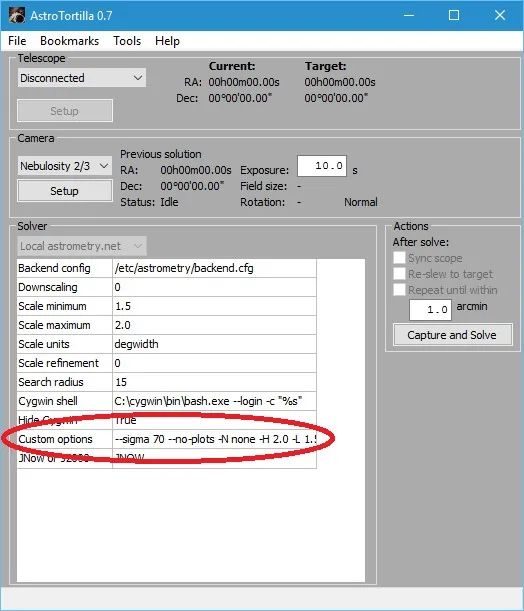

AstroTortilla: Custom Options 2Due to the length, you cannot see the entire Custom options line in the above screenshot. For reference, it reads:

–sigma 70 –no-plots -N none -H 2.0 -L 1.5 -r –objs 100

The same settings under Camera are kept, using Nebulosity 2/3, the QSI 500/600 camera and Binning at 2 (for me personally, of course). I now save these settings to a new settings file, naming it appropriately.

Abbildung 19: AstroTortilla: Save Settings (Google Drive AstroTortilla_6379424_orig.jpg)

Vergleiche Abbildung 15  AstroTortilla_4482496_orig.jpg
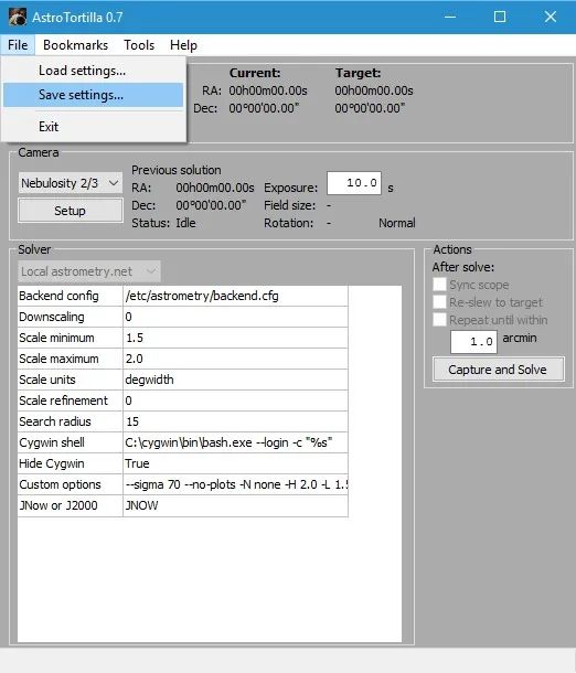

AstroTortilla Save Settings 2

Abbildung 20: AstroTortilla Save Settings File 2 (Google Drive AstroTortilla_3770875_orig.jpg)

Vergleiche Abbildung 16 AstroTortilla_8117221_orig.jpg


AstroTortilla Save Config File 2

I have now customised AstroTortilla for both my telescopes and their resulting fields of view. Depending on my imaging setup on a particular night, I can load up the appropriate settings file. These settings optimise the plate solving process to make it significantly faster and always yield a solution. You may need to alter exposure time to suit if a solution is not found when plate solving or it seems to be taking too long. For reference, plate solving should normally take under 2 minutes to perform in total.

If for any reason the stars in your images are not coming out round and plate solving is therefore failing (optical defects, collimation, focus, etc), you can add another Custom option to relax AstroTortilla’s restriction on what constitutes a star. The command for this is -c, which needs to be followed by a value. As a default, AstroTortilla uses -c 0.01 but if you wish to relax this a little, you can add -c 0.02 to your Custom options. If you increase it, do so by very small amounts, like -c 0.02.

3. Using AstroTortilla for Plate Solving

With the appropriate settings file loaded (for the imaging setup being used), the first thing we need to do is connect to our telescope mount via ASCOM. So, we select ASCOM Telescope from the list at the top and then confirm via the ASCOM dialog that pops up (I am using the simulator for this tutorial!).

Abbildung 21: AstroTortilla: ASCOM Telescope (Google Drive AstroTortilla_1842666_orig.jpg)


AstroTortilla: Connect ASCOM Telescope

Abbildung 22: AstroTortilla: ASCOM Telescope Chooser (Google Drive: AstroTortilla_5503543_orig.jpg)


AstroTortilla: ASCOM Telescope Chooser

Once connected to the telescope, I issued a goto command in Stellarium to slew the telescope to the Veil Nebula.

Abbildung 23: AstroTortilla: Goto Veil Nebula (Google Drive Stellarium_1474865_orig.jpg)


AstroTortilla: Goto Veil Nebula

Abbildung 24: AstroTortilla Current/Target (Google Drive: AstroTortilla_2629214_orig.jpg)


AstroTortilla Current/Target

With the telescope on target, you can gauge an idea of the error under Telescope within AstroTortilla (comparing Current to Target co-ordinates). In a real-life situation, the difference here will be much bigger (remember I am using the simulator for this tutorial!). With Tracking displayed under Target, we are ready for plate solving.

Now we will need to connect to the CCD camera. You have a choice of what to do here. Open your program and connect to the CCD camera within the program. Once connected to the CCD camera, select the program from the list in AstroTortilla if you have not done so beforehand (when you created your settings file).

It is important to start the program and connect to your CCD camera beforehand as AstroTortilla will issue commands to the program itself to start capture, after which it will download the resulting image and start the plate solving. If your program is not listed on AstroTortilla or for some reason is not working as intended, you can always capture the image yourself within your program and save it somewhere. Then in AstroTortilla, select File Open dialog for Camera and later when we start plate solving, it will ask you to open the image file. This ensures AstroTortilla is very universal. You can also of course, connect to your CCD camera directly by selecting ASCOM Camera and then selecting the appropriate driver from the list, which will be installed if you have used your CCD camera in the past. If you are having AstroTortilla capture and download the image itself (and not providing one via the File Open dialog), set an appropriate exposure time as well. 10 seconds tends to be very suitable and you are advised not to make exposures too long, though you can also do 20 seconds or so. Under 1 minute is always good.

Before starting plate solving, check Sync scope and Re-slew to target under Actions. The first ensures an alignment point is added to the likes of EQMod (this acts like a star alignment, which makes future goto commands more precise). The second ensures the target is physically centred after AstroTortilla plate solves, which is the main idea behind us even using AstroTortilla to begin with.

Abbildung 25: AstroTortilla: Capture and Solve (Google Drive: AstroTortilla_5584514_orig.jpg)


AstroTortilla: Capture and Solve

To start plate solving, all we need to do now is click the Capture and Solve button and watch it happen. In my experience, one plate solving iteration centers my objects perfectly but if you want to be very precise about it, check the third option Repeat until within and enter a respective accuracy in arcminutes. Please note that this will cause the plate solving process to be repeated again and again until the desired accuracy is achieved. At the very minimum, two plate solving processes will occur – the first to perform the initial centering to your target and the second to check that it is within desired accuracy. Speaking from personal experience, I find my target is always precisely centred in the field of view of my camera without using the Repeat until within option, with a single plate solve.

In any case, when happy, click Capture and Solve. AstroTortilla will first capture your image, download it and start plate solving (if you chose to provide an image file yourself via File Open dialog, it will just ask you for the image file). The plate solving process starts by searching its astrometric index files (the ones you downloaded for installation) for a match, calculating how far off you are, slewing your telescope appropriately and syncing the difference as a goto alignment point in EQMod. Subsequent iterations of this process are up to you (dependent on your chosen accuracy for repetition).

This concludes how to use AstroTortilla. It really is that easy and after having customised it for your possible telescope setups, plate solving should be a fast process. Do make sure you play around with exposure time if a solution is not yielded with a 10 second exposure but remember that under 1 minute is good. Too long an exposure time will basically take longer to capture and will not really be necessary for plate solving. You can of course play around with the –sigma value here as well. Decrease it to include more stars and increase it to reject dimmer stars.

4. Further Optimising Plate Solving Speed

After you have used AstroTortilla to plate solve successfully a couple of times, you will notice a pattern. Since you have a large number of astrometric index files downloaded and stored for plate solving, AstroTortilla will look through them all until it finds a match to your exposure and then does its magic. If you look closely, it will seem that it will always find a match for your particular telescope-camera pair in one astrometric index file, or two or three, but never seems to make use of the other astrometric index files. This is normal. During the installation, a lot of astrometric index files were downloaded as per your field of view limitations. Most of these however, are not needed (as evidenced by your plate solving successes). We can use this fact to produce a further speed optimisation to plate solving.

To accurately determine which astrometric index files are useful, one must use the Log Viewer by going to the Tools menu and clicking Log Viewer. This will open a new, small window on the side.

Abbildung 26: AstroTortilla: Tools -> Log Viewer (Google Drive: AstroTortilla_1079311_orig.jpg)


AstroTortilla: Tools -> Log Viewer

Abbildung 27: AstroTortilla Log Viewer Window (Google Drive: AstroTortilla_1219258_orig.jpg)


AstroTortilla LogViewer Window

Keep Info selected from the list and now carry out your plate solving as usual. The events that appear and disappear quickly on the very bottom of AstroTortilla will be listed in sequence in the the Log Viewer. You can scroll through them to see what has happened over time. You can also scroll right to see which astrometric index file was being looked at, at the time.

Abbildung 28: AstroTortilla Log Viewer (Google Drive AstroTortilla_1333089_orig.jpg)


AstroTortilla Log Viewer

Abbildung 29: AstroTortilla LogWindow (Google Drive: AstroTortilla_5341826_orig.jpg)


AstroTortilla LogWindow filledEventually it will successfully plate solve and it will tell you so, showing you which astrometric index file was the successful one in matching your exposure. Take note of the astrometric index file name. Please do remember that from one target to the next, it may end up plate solving successfully with another astrometric index file, though usually this is an adjacent one (e.g. it may normally succeed using index-4206-11.fit but another night on another region of the night sky it will succeed using index-4206-10.fit). Normally it appears two or three astrometric index files does the job for a particular telescope-camera pair. Do note that, as in my case, if you use different telescope-camera pairs, you will no doubt have a couple of useful astrometric index files per telescope-camera pair.Once you have determined which astrometric index files do it for you, you can physically move the unused ones out of the usual folder so that they are missing during plate solving and thus AstroTortilla does not waste time in looking through them (as they are useless to you anyway). To access the astrometric index files you have, assuming you installed everything in its default directories, go to the following folder:
C:\cygwin\usr\share\astrometry\data

Abbildung 30: AstroTortilla: Folder for Index files (Google Archiv: AstroTortilla_6838327_orig1.jpg)


AstroTrortilla Folder for Index Files

There are clearly a good number of astrometric index files there, as per my installation of AstroTortilla. Now, let us say we determined that actually only the following were useful for me:

  • index-4206-09.fit
  • index-4206-10.fit
  • index-4206-11.fit

It is then a simple process of selecting all the other astrometric index files (just the files with .fit as file extensions) and moving them to a custom sub-folder I made, named Not Useful.

Abbildung 31: AstroTortilla: Index Files (Google Drive: AstroTortilla_7677656_orig.jpg)


AstroTortilla Not Usefull Index Files

Abbildung 32: AstroTortilla Index Files (Google Drive: AstroTortilla_9821654_orig.jpg)


AstroTortilla Index Files

Abbildung 33: AstroTortilla Index Files (Google Drive AstroTortilla_6006521_orig.jpg)


AstroTortilla Index Files Not Useful

Abbildung 34: AstroTortilla Index Files (Google Drive AstroTortilla_9351208_orig.jpg)


AstroTortilla Index Files Useful

Above I demonstrate the created Not Useful folder, selection of all astrometric index files except the useful ones, moving the selected ones to the Not Useful folder and then how the only available astrometric index files are now the ones I deemed useful. By experience, this should make a plate solve that usually takes around 30 seconds (as reported by AstroTortilla) succeed in just under 5 seconds. That is certainly a big deal. The reason the astrometric index files are not just simply deleted is because we may actually need them in the future, which brings us to the caveat of this optimisation technique

The caveat is that if you do not experiment with plate solving enough to know which astrometric index files are really useful, you may end up moving a useful one inadvertedly and thus causing plate solving to fail on that particular target. This is a simple thing to fix however. Simply access the Not Useful folder and move one astrometric index file back over. Choose one that is above or below the ones you currently have available. For example, if I have the above three but plate solving failed, I would choose to move back either index-4206-08.fitor index-4207-00.fit. I would move only one and retry plate solving until it succeeds as there is no point in deviating too far from the usually useful astrometric index files or introducing too many new ones into our availability pile.

One final note is that since you are already in the folder storing all your .fit astrometric index files, you may as well back them up somewhere. If you choose to re-install AstroTortilla for any reason, you can skip ahead and not download any astrometric index files. Instead, you can copy-paste your backup of all your .fit files in place. This saves a lot of time when it comes to installing AstroTortilla​.

5. Things to Try when Plate Solving Fails to Centre the Target or Fails Completely

Though this tutorial has thus far covered what astrometric index files to download and how to correctly configure AstroTortilla, there are always reports of users who experience nothing but failed plate solve events, or not centering the target as perfectly as intended. If AstroTortilla is succeeding at plate solving and appears to not really centre your target, instead placing it consistently off-centre, then your problem is related to different epochs being used by the mount and AstroTortilla. The epochs users can select from most software are J2000 and JNow. By default, AstroTortilla uses the JNow​ epoch.

Abbildung 35: AstroTortilla: Epoch (Google Drive AstroTortilla_5343608_orig.jpg)


AstroTortilla: Epoch JNow

This is fine so long as your mount is also using JNow, for example. If you are using EQMod to control your mount, then you can set the mount epoch you want under Driver Setup in the EQModToolbox.

Abbildung 36: AstroTortilla Epoch in EQMOD (Google Drive: EQASCOM-01.jpg)


AstroTortilla: Epoch EQMOD Setup

Abbildung 37: AstroTortilla Epoch EQMOD Setup (Google Drive: AstroTortilla_2928268_orig.jpg)


AstroTortilla: Epoch EQMOD Setup

The key is simply making sure both your mount’s and AstroTortilla’s epochs agree. This way the goto error correction command sent by AstroTortilla to the mount is interpreted as intended. There is no specific advantage to using JNow over J2000 however, so do not stress about this.

What happens if AstroTortilla appears to be successfully plate solving your target but then gets stuck on the “Re-centering“process and your mount does nothing? This is a common issue that tends to be fixed by parking the mount, switching it off, switching it back on and trying again. However, at times the problem is stubborn, or you may not want to park the mount and cycle its power. This is fixed by stopping EQMod from storing the star alignment points when AstroTortilla sends the Sync command. All you have to do is select Dialog Based under User Interface in Alignment / Sync. You should also click the Clear Align Data button to delete all star alignment points saved thus far.

Abbildung 38: AstroTortilla EQMOD SYNC (Google Drive: AstroTortilla_5495740_orig.jpg)


AstroTortilla SYNC EQMOD

The default setting on User Interface in Alignment / Sync on EQMod is Append on Sync. This setting adds new star alignment points when an ASCOMSync command is sent by software such as AstroTortilla (or Stellarium through StellariumScope, for example). The setting Dialog Based allows users to manually enter star alignment point data. This ignores all ASCOMSync commands and therefore fixes the “Re-centering getting stuck issue in AstroTortilla​.

The above covers if AstroTortilla plate solves but does not successfully centre your target. However, what if AstroTortilla does not plate solve at all? The common error here is “Field 1 did not solve”, usually after several minutes of frustrating wait. The first thing to try is to increase the exposure time on AstroTortilla (or the image capture software you are using). First however, make sure you are not using a narrowband filter in front of your sensor (if using a monochrome CCD camera).

Abbildung 39: AstroTortilla Exposure Time (Google Drive: AstroTortilla_3984117_orig.jpg)


AstroTortilla Plate Solving Exposure Time

I have personally always found 20 seconds to suffice with a Luminance filter, looking through telescopes that range between f/4.5 and f/5.5 focal ratio. If this does not work, you can try lowering the value on the –sigma parameter under Custom options. By lowering –sigma, more objects detected in your exposure will be treated as stars for comparison with the astrometric index files. If your current value is 70, you could try values such as 50, 30, 20, etc. Avoid values lower than about 10 however.

Abbildung 40: AstroTortilla Custom Options: Sigma (Google Drive: AstroTortilla_4490212_orig.jpg)


AstroTortilla Custom Options Sigma

If your exposure time has been increased and your –sigma value has been decreased but you are still not getting plate solving to work, you may wish to expand the Search radius. 15 should work perfectly well but this can be increased to 30 or even 45. You should not need to go this high but there is nothing wrong with values of 45 or lower.

Abbildung 41: AstroTortilla: Search Radius (Google Drive: AstroTortilla_5329735_orig.jpg)


AstroTortilla Solver Search Radius 30

In the unfortunate scenario that you are still having problems plate solving with AstroTortilla, it is time to look at the astrometric index files again. By default, AstroTortilla downloads the 4200 series of astrometric index files, which are based on the 2MASS star catalog. However, in particular for wide-field setups, the 4100 series of astrometric index files can be much better. These are based on the Tycho2 star catalog. Downloading these can be done by running the AstroTortilla​ installer again, selecting only to install additional astrometric index files.

Abbildung 42: AstroTortilla Additional Index Files (Google Drive: AstroTortilla_5562525_orig.jpg)


AstroTortilla Additional Index Files

On the next screen, you need to check to enable the option ​”Tycho2 indexes for FOVs over 3 degrees (339MB)”​.

Abbildung 43: AstroTortilla Tycho2 Index Files (Google Drive: AstroTortilla_6437877_orig.jpg)


AstroTortilla Tycho2 Index Files

Enabling this option will disable the astrometric index file selection below it. Do not worry. Continuing the setup will actually download the entire set of 4100 series of astrometric index files, at only about 339MB. Once these are downloaded, it is worth trying plate solving once again.

If it works, you could then refine your settings again. Perhaps with the 4100 series of astrometric index files downloaded, you can use a Custom options setting of –sigma 70 and Search radius of 15​. Though not required to download new astrometric index files (as you can use the AstroTortilla setup to do this), you can access these files directly at the Astrometry.net addresses for the 4100 series and 4200 series astrometric index files (click links). At these addresses, you may download the individual astrometric index files and place them in their required folder:

  • C:\cygwin\usr\share\astrometry\data

Comments

(Feb 24, 2016) kayronjm (mod) said:
@Steve Mills,Hi Steve,I see what you mean. You want to download FURTHER astrometric index files in addition to the ones you already have. To do this, simply run AstroTortilla’s installer again, but don’t uninstall what you have. Run the installer and when it asks what components you wish to install, simply select “Install additional astrometric index files”. In the next screen, simply set what you want OVERALL, even if you already have some. Choose the range you now want to have, and the installer will check what files you already have and only download the missing ones (the new files). That’s it – once done, you’re good to go. Remember to re-configure AstroTortilla with the new combination’s settings for FOV.

Best Regards,Kayron

(Feb 24, 2016) Steve Mills said:
Once you enter the info on the setup screen, how do you get back to that screen to re-enter DIFFERENT “widest” and “narrowest” data if you change scopes and/or cameras?

(Dec 28, 2015) Magnus Kvant said:

Super! The only problems I’ve had are really related to the telescope.
Make sure the Polar alignment is very precise, otherwise Astrotortilla will contunue to reslew indefinitely until it stops.
A sudden cloud or loss of focus will obviously make AT to fail!
These things go without saying obviously, but may be forgotten in the heat of the moment.
===